semi合集-English.pdf - 第4981页
SEMI M12-1103 © SEMI 1988, 2003 3 6.3 An exam ple of the code is gi ven in Fig ure 2. 6.4 SEMI-OCR St andard Character Set — This character set contains capital letters from A to Z, numerals from 0 to 9, a dash, and a pe…
SEMI M12-1103 © SEMI 1988, 2003 2
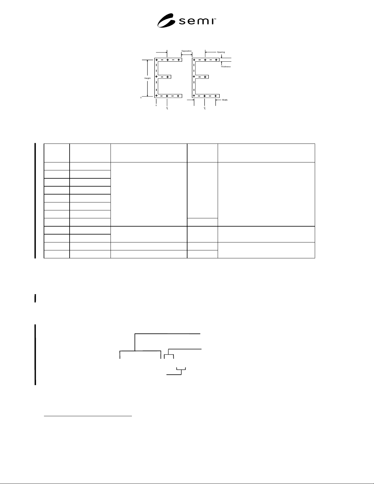
Figure 1
Character Outline
Table 2 Code
Character
Location
CharacterStyle Parameter Code Definition
1 Alpha/Numeric
2 Alpha/Numeric
3 Alpha/Numeric
4 Alpha/Numeric
5 Alpha/Numeric
6 Alpha/Numeric
7 Alpha/Numeric
A through Z
and
0 through 9
8 Numeric Only
IDENTIFICATION NUMBER
0 through 9
Supplier-Assigned (see Note 1)
9 Alpha Only
10 Alpha Only
WAFER SUPPLIER
IDENTIFICATION
A through Z (see SEMI AUX001
1
and Note 1)
11 Alpha Only CHECK CHARACTER A
11
A through H
12 Numeric Only CHECK CHARACTER A
12
0 through 7
Error-Detecting Method (see Section 9)
NOTE 1: In the absence of information at any assigned location, a dash (–) must be used.
1 SEMI AUX001, List of Wafer Supplier Identification Codes, available from SEMI web site: www.semi.org.
6 Alphanumeric Code
6.1 The code consists of one line of 12 characters. The first eight characters are an identification number which is
unique to the wafer for a given vendor. These characters may be alphanumeric except character 8 which must be
numeric (see Table 2). Characters 9 and 10 comprise the supplier identification code (see SEMI AUX001
1
).
Characters 11 and 12 are check characters (see Section 9). These check characters are machine generated for code
acceptance and reading verification.
Identification Number
Wafer
Supplier
Identification
Code
Check Characters
12345678ABC1
Figure 2
Example of Code
6.2 In the absence of a character at any assigned location, a dash (–) must be used.
SEMI M12-1103 © SEMI 1988, 2003 3
6.3 An example of the code is given in Figure 2.
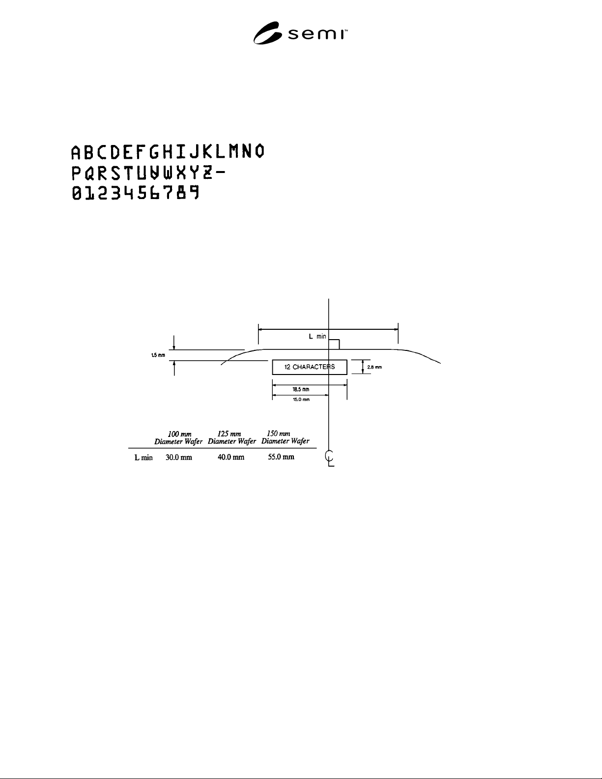
6.4 SEMI-OCR Standard Character Set — This character set contains capital letters from A to Z, numerals from 0
to 9, a dash, and a period (see Appendix 1). The period is NOT used in the code symbols defined in this
specification (see Tables 2 and 3), although it is required for use in the code symbols defined in SEMI M13.
Table 3 SEMI OCR Character Set Modified for Use in this Specification
7 Character Window
7.1 The character window must be located on the front surface of the wafers.
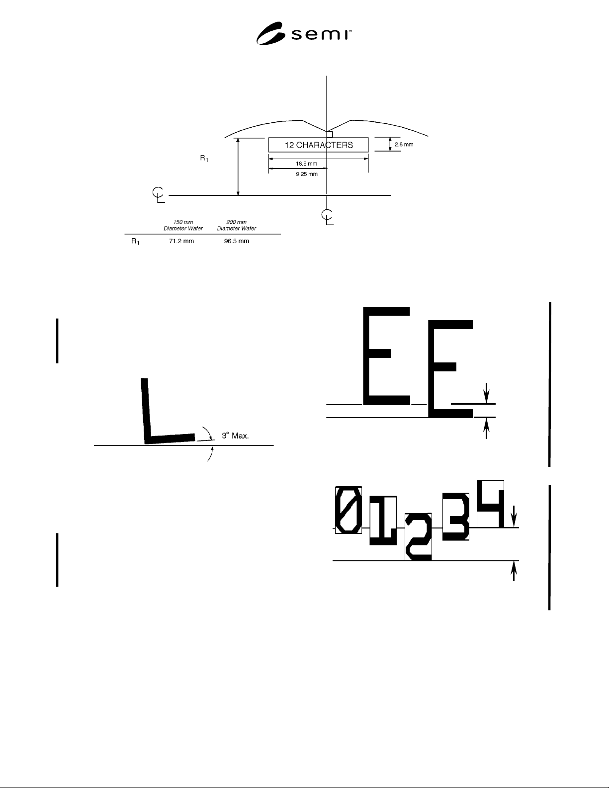
7.2 All characters must be contained within the character window dimensions specified in Figures 3 (for flatted
wafers) or Figure 4 (for notched wafers).
7.3 The top of the characters is toward the side of the character window nearest to the flat or notch.
Figure 3
Character Window Location for Flatted Wafers
NOTE: The vertical center line referenced in Figure 3 is the bisector of the primary fiducial (flat).
SEMI M12-1103 © SEMI 1988, 2003 4
Figure 4
Character Window Location for Notched Wafers
NOTE: The vertical center line referenced in Figure 4 is the bisector of the primary fiducial (notch).
8 Character Alignment
8.1 Character Skew — the maximum allowable angle
between the character baseline and a line parallel with
the bottom of the character window shall be 3 degrees
(see Figure 5).
Figure 5
Character Skew
NOTE: This line is parallel to the bottom of the character
window.
8.2 Maximum Character Misalignment — the
maximum adjacent character misalignment, R
adj
shall
be 0.23 mm (see Figure 6), and the maximum line
character misalignment, R
line
, shall be 0.46 mm (see
Figure 7).
R
adj
Figure 6
Adjacent Character Misalignment
R
line
Figure 7
Line Character Misalignment