semi合集-English.pdf - 第5136页
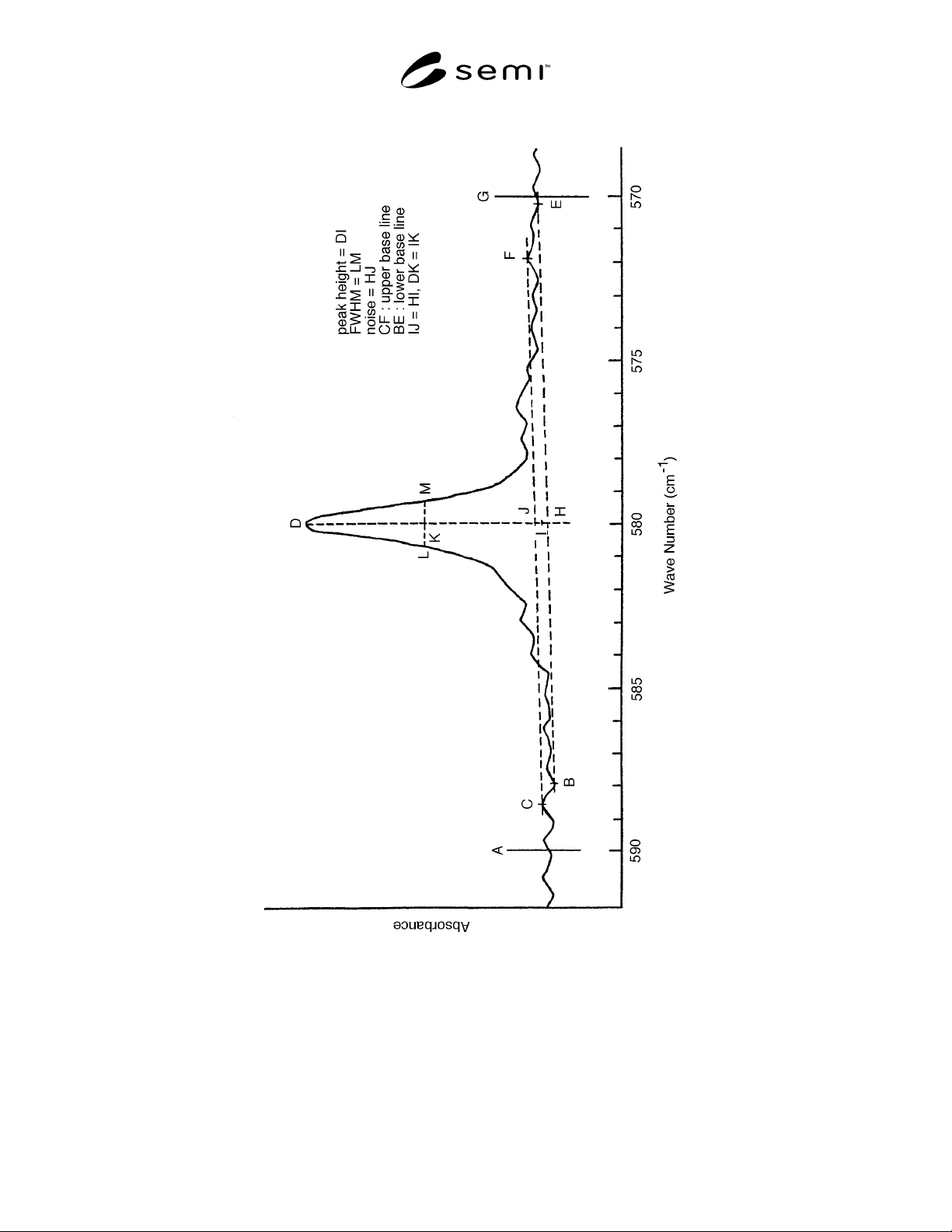
SEMI M30-0997 © SE MI 1997 2 Figure 1 FT-IR Spectrum of C as Local Mode Absorption in GaAs

SEMI M30-0997 © SEMI 19971
SEMI M30-0997
STANDARD TEST METHOD FOR SUBSTITUTIONAL ATOMIC CARBON
CONCENTRATION IN GaAs BY FOURIER TRANSFORM INFRARED
ABSORPTION SPECTROSCOPY
1 Purpose
The purpose of this document is to test substitutional
atomic carbon concentration in GaAs by Fourier
Transform Infrared Absorption Spectroscopy (FT-IR).
2 Scope
2.1 This referee test method cover s the determination
of substitutional carbon concentration in single crystal
GaAs.
2.2 The useful range of carbon con centration
measurable at room temperature by this test method is
from the maximum amount of substitutional carbon
soluble in GaAs to 1 × 10
15
cm
-3
. The detection limit
depends on the equipment and measurement conditions.
It is expected that many users of this test method can
reduce the detection limit to 10
14
cm
-3
level. 77K
measurement is effective to reduce the detection limit.
In the case of 77K measurement, the upper limit is 1.3
× 10
16
cm
-3
, as described in the following article:
T.Arai et al : J. Electronic Industry, Vol. 30, 9
(1988) 38
2.3 The test method utilizes the relationship between
carbon concentration and absorption coefficient at 580
cm
-1
for room temperature measurement (around 582
cm
-1
for 77K measurement), the infrared absorption
band is associated with substitutional carbon in GaAs.
These specific absorption bands in GaAs have been
associated with the local vibration mode of C
as
.
2.4 The method is applicable to Se mi-Insulating (SI)
GaAs. Slices can be any crystallographic orientation
and should be polished or lapped and etched on both
surfaces.
2.5 This test method is intended to be used with FT-IR
spectrometers that are equipped to operate in the region
including the wave number range from 700 to 500 cm
-1
.
2.6 This standard may involve haz ardous materials,
operation, and equipment. This standard does not
purport to address all of the safety problems associated
with its use. It is the responsibility of the user of this
standard to establish appropriate safety and health
practices and determine the applicability of regulatory
limitations prior to use.
3 Referenced Documents
3.1 ASTM Standards
1
E 131 — Definitions of Terms and Symbols Relating to
Molecular Spectroscopy
E 168 — Recommended Practices for General
Techniques of Infrared Quantitative Analysis
E 177 — Practice for Use of the Terms Precision and
Bias in ASTM Test Methods
F 120 — Practice for Infrared Absorption Analysis of
Impurities in Single Crystal Semiconductor Materials
F 133 (A 894) — Test Method for Thickness and
Thickness Variation of GaAs Slices
3.2 Other Document
2
DIN 50449-1 — Bestimmung des
Verunreinigungsgehaltes in III-V-
Verbindungshalbleitern mittels Infrarotabsorption/Teil
1: Kohlenstoff in Galliumarsenide (Determination of
Impurity Content in Semiconductors by Infrared
Absorption Part 1: Carbon in Gallium Arsenide)
4 Terminology
4.1 Acronyms
4.1.1 CPAA — Charged particle activation analysis
4.1.2 FWHM — Full width at half maximum, the
width of the absorption band at half its magnitude as
measured from the baseline.
4.1.3 MCT — Mercury cadmium tel luride
4.1.4 TGS — Triglycine sulfate
4.2 Many of the terms associated with this test method
can be found in ASTM Definitions E 131.
4.2.1 baseline — A linearly interpol ated pattern over a
limited spectral region of the ratio recording used to
derive an absorption coefficient (see Figure 1 and refer
to ASTM Practice E 168).
1 American Society for Testing and Materials, 100 Barr Harbor
Drive, West Conshohoken, PA 19428-2959
2 Deutches Institut fur Normung, e.v., Beuth Verlag GmbH,
Burggrafstrasse 4-10, D-1000 Berlin 30, Germany
SEMI M30-0997 © SEMI 1997 2
Figure 1
FT-IR Spectrum of C
as
Local Mode Absorption in GaAs
SEMI M30-0997 © SEMI 19973
4.2.2 calibration coefficient — Conversion factor to
carbon concentration from absorbance or absorption
coefficient of each FT-IR instrument.
4.2.3 carbon concentration — For purposes of this test
method, the volume density of atomic carbon
incorporated in the crystal lattice at substitutional
positions. It is proportional to the absorption coefficient
following Beer’s law. Units are atoms per cubic
centimeter.
4.2.4 primary standard samples — Samples where the
carbon concentration is already known, as measured by
the CPAA method (see Section 4.1.1). A set of primary
standard samples is composed of 4 specimens with each
carbon concentration as follows:
No. Thickness (mm) Carbon Concentration (cm
-3
)
#3 5.103 1.4 x 10
15
#5 5.013 12.0 x 10
15
#7 5.015 2.4 x 10
15
#15 4.994 3.2 x 10
15
These samples are preserved at SEMI Japan. Details
(actual measured values and measurement errors, etc.)
for these samples are described in the following article:
T.Arai et al : J. Electronic Industry, Vol. 30, 9
(1988) 38
4.2.5 reference sample — The nearly carbon-free
GaAs sample used for calculating the subtracted
spectrum which are used for determination of carbon
concentration. The reference sample is used for room
temperature measurement. It is recommended that the
carbon concentration of the reference sample is < 3 ×
10
14
cm
-3
.
4.2.6 secondary standard samples — The samples of
which the carbon concentration was determined in a
round-robin test by the FT-IR method using the primary
standard samples. More than 3 samples covering the
carbon concentration range from 1.5 × 10
15
to 10.0 ×
10
15
cm
-3
must be used. These samples are preserved as
SEMI Japan, and will be lent out for determination of
the calibration coefficient for specific FT-IR
spectrometers.
5 Summary of Test Method
5.1 Test slices are prepared that are polished or lapped
and etched on both sides to a thickness from 3 to 6 mm.
5.2 Apparatus should be calibrated by using the
primary standard samples or secondary standard
samples. This calibration coefficient is used to calculate
the carbon concentration of specimens.
5.3 For room temperature measure ment, a baseline is
drawn in the differential spectrum (after subtraction of
the reference sample spectrum) from which an
absorption coefficient is derived. The range of baseline
should be wider than ± 10 cm
-1
. The baseline has to be
determined in an interval of the spectra which is neither
influenced by main peak at 580 cm
-1
nor the side peak
at 576 cm
-1
. For 77K measurement, the range of
baseline should be wider than ± 1.5 cm
-1
.
6 Significance and Use
6.1 Carbon plays an important role in the
determination of the compensation mechanism which
determines the semi-insulating behavior of GaAs. As
such the concentration is critical in determining the
substrate resistivity.
6.2 As a dominant acceptor in SI-GaAs substrates,
carbon could, potentially impact ion implantation
activation.
7 Interferences
7.1 Stray light that reaches the det ector will tend to
reduce the calculated absorption coefficient value and
thereby reduce the reported carbon concentration.
7.2 FT-IR instrument instruction m anuals should be
consulted if problems with the technique are suspected.
7.3 The carbon absorption band ha lf width at room
temperature must be less than 2 cm
-1
for acceptable
measurement results. Excessive width can be due to
improper thickness matching or stress.
7.4 Specimens that do not exceed the instrument beam
size will cause error. Use of apertures, or preferably
beam condensers, can correct this problem.
7.5 The minimum detection level of this method is
limited by the signal-to-noise ratio of the recording.
8 Apparatus
8.1 FT-IR with an operating range that includes the
region of 700 to 500 cm
-1
. Instrument resolution or
spectral resolution at the carbon absorption band of 580
cm
-1
for room temperature measurement and around
582 cm
-1
for 77K measurement must not exceed 0.5 cm
-
1
, which means the effective resolution after
apodization must not exceed 1.0 cm
-1
.
8.1.1 Beam sizes and sample holder active areas for
both the specimen and the reference must be within
10% of each other.
8.2 Instrument suitable for thickne ss measurement to
an accuracy of 0.0025 mm.