semi合集-English.pdf - 第5137页
SEMI M30-0997 © SE MI 1997 3 4.2.2 calibration coefficien t — Conv e r sion factor to carbon con centration from abs orbance or absorption coefficient of each FT-IR instrument. 4.2.3 car bon concentration — F or p u r po…
SEMI M30-0997 © SEMI 1997 2
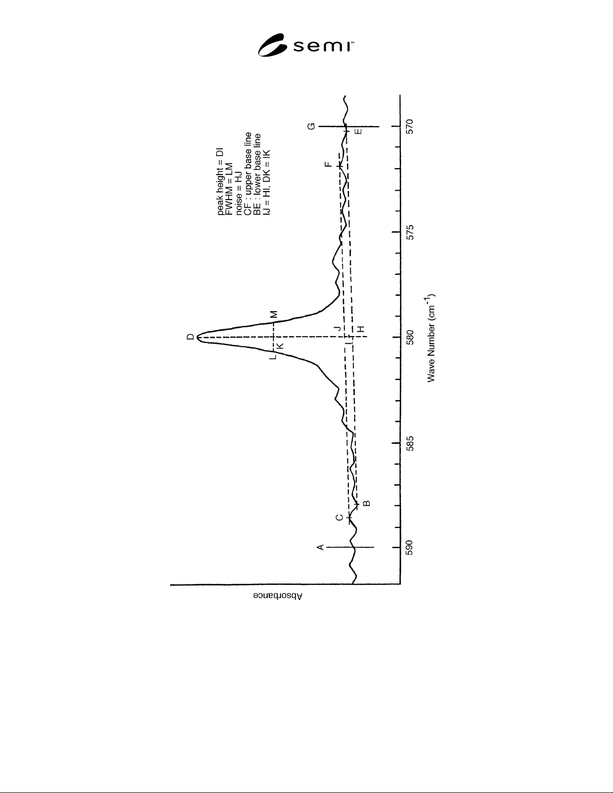
Figure 1
FT-IR Spectrum of C
as
Local Mode Absorption in GaAs
SEMI M30-0997 © SEMI 19973
4.2.2 calibration coefficient — Conversion factor to
carbon concentration from absorbance or absorption
coefficient of each FT-IR instrument.
4.2.3 carbon concentration — For purposes of this test
method, the volume density of atomic carbon
incorporated in the crystal lattice at substitutional
positions. It is proportional to the absorption coefficient
following Beer’s law. Units are atoms per cubic
centimeter.
4.2.4 primary standard samples — Samples where the
carbon concentration is already known, as measured by
the CPAA method (see Section 4.1.1). A set of primary
standard samples is composed of 4 specimens with each
carbon concentration as follows:
No. Thickness (mm) Carbon Concentration (cm
-3
)
#3 5.103 1.4 x 10
15
#5 5.013 12.0 x 10
15
#7 5.015 2.4 x 10
15
#15 4.994 3.2 x 10
15
These samples are preserved at SEMI Japan. Details
(actual measured values and measurement errors, etc.)
for these samples are described in the following article:
T.Arai et al : J. Electronic Industry, Vol. 30, 9
(1988) 38
4.2.5 reference sample — The nearly carbon-free
GaAs sample used for calculating the subtracted
spectrum which are used for determination of carbon
concentration. The reference sample is used for room
temperature measurement. It is recommended that the
carbon concentration of the reference sample is < 3 ×
10
14
cm
-3
.
4.2.6 secondary standard samples — The samples of
which the carbon concentration was determined in a
round-robin test by the FT-IR method using the primary
standard samples. More than 3 samples covering the
carbon concentration range from 1.5 × 10
15
to 10.0 ×
10
15
cm
-3
must be used. These samples are preserved as
SEMI Japan, and will be lent out for determination of
the calibration coefficient for specific FT-IR
spectrometers.
5 Summary of Test Method
5.1 Test slices are prepared that are polished or lapped
and etched on both sides to a thickness from 3 to 6 mm.
5.2 Apparatus should be calibrated by using the
primary standard samples or secondary standard
samples. This calibration coefficient is used to calculate
the carbon concentration of specimens.
5.3 For room temperature measure ment, a baseline is
drawn in the differential spectrum (after subtraction of
the reference sample spectrum) from which an
absorption coefficient is derived. The range of baseline
should be wider than ± 10 cm
-1
. The baseline has to be
determined in an interval of the spectra which is neither
influenced by main peak at 580 cm
-1
nor the side peak
at 576 cm
-1
. For 77K measurement, the range of
baseline should be wider than ± 1.5 cm
-1
.
6 Significance and Use
6.1 Carbon plays an important role in the
determination of the compensation mechanism which
determines the semi-insulating behavior of GaAs. As
such the concentration is critical in determining the
substrate resistivity.
6.2 As a dominant acceptor in SI-GaAs substrates,
carbon could, potentially impact ion implantation
activation.
7 Interferences
7.1 Stray light that reaches the det ector will tend to
reduce the calculated absorption coefficient value and
thereby reduce the reported carbon concentration.
7.2 FT-IR instrument instruction m anuals should be
consulted if problems with the technique are suspected.
7.3 The carbon absorption band ha lf width at room
temperature must be less than 2 cm
-1
for acceptable
measurement results. Excessive width can be due to
improper thickness matching or stress.
7.4 Specimens that do not exceed the instrument beam
size will cause error. Use of apertures, or preferably
beam condensers, can correct this problem.
7.5 The minimum detection level of this method is
limited by the signal-to-noise ratio of the recording.
8 Apparatus
8.1 FT-IR with an operating range that includes the
region of 700 to 500 cm
-1
. Instrument resolution or
spectral resolution at the carbon absorption band of 580
cm
-1
for room temperature measurement and around
582 cm
-1
for 77K measurement must not exceed 0.5 cm
-
1
, which means the effective resolution after
apodization must not exceed 1.0 cm
-1
.
8.1.1 Beam sizes and sample holder active areas for
both the specimen and the reference must be within
10% of each other.
8.2 Instrument suitable for thickne ss measurement to
an accuracy of 0.0025 mm.

SEMI M30-0997 © SEMI 1997 4
8.3 Holders for these test and refer ence specimens that
prevent any source of infrared radiation from bypassing
the specimen.
8.4 For use at 77K, low-temperature cryostat capable
of maintaining the specimen and reference at 77K
temperature with suitable window materials (refer to
ASTM Practice F 120).
8.5 Equipment and materials for s licing and polishing
GaAs to a final thickness tolerance of 0.005 mm or less,
and a total thickness variation of 0.01 mm or less.
9 Sampling
Unless otherwise specified, a GaAs slice used for the
carbon test is to be measured at the nominal slice
center. And if a slice is to be reduced in area prior to
test, it is shaped such that the original slice center area
is that which is tested.
10 Test Specimens
10.1 A single crystal slice of GaAs with a thickness
from 3 to 6 mm must be used for carbon determination.
10.2 The test specimen must be carefully shaped to the
following criteria:
10.2.1 Thickness variation over the m easurement area
of 0.005 mm or less.
10.2.2 Same surface preparation on both front and
back surfaces. For room temperature measurement,
surface preparation of specimen should be same with
reference sample. For 77K measurement, mirror
polishing on both surface or same surface preparation
with standard sample is recommended.
10.2.3 Final thickness agreement betw een specimen
and reference samples of 0.1 mm.
10.2.4 Surface area large enough such that with
respect to the holders no incident radiation can bypass
either specimen or reference.
11 Procedure
11.1 Prepare FT-IR in accordance with the
manufacture’s instructions.
11.2 Determine the differential tran smission spectrum
from 700 to 500 cm
-1
in accordance with of ASTM
Practice F 120.
11.2.1 The FWHM must not exceed 2 cm
-1
to achieve
reliable results. If this is not met, recheck test and
reference specimen mechanical properties, use slower
scan speed, or longer measuring time, and reverify FT-
IR operating conditions.
11.2.2 Reference to Figure 1 and Recommended
ASTM Practice E 168, Section 7, for assistance in
establishing a baseline on the finished spectrogram.
Baseline determination is very important to this
method, and becomes more critical as the measured
carbon level decreases (refer to ASTM Practice E 168).
11.2.3 For room temperature meansurement, the
following conditions are recommended:
• Detector : Broadband MCT (or TGS) (see Sections
4.1.3 and 4.1.4)
• Resolution : 0.5 cm
-1
• S/N ratio : > 3
• Range of wave number : including 700 – 500 cm
-1
• Aperture : Optimum for each FT-IR
• Apodization function : Triangle
• Smoothing : Not applicable
• Reference : Air, reference sample
• Temperature : 290 ~ 300K
11.2.4 Make the determination at low temperature
(77K) if increased sensitivity is required. Follow the
same test conditions as described in Sections 11.1 and
11.2 except reference and temperature.
11.3 Determination of the calibratio n coefficient
should be done once or more times per year. Four or
more secondary standard samples should be used for
this calibration. The user of this method can have and
use the internal standard samples to check the
spectrometer frequently.