semi合集-English.pdf - 第5447页
SEMI M60-0305 © SEMI 2005 15 R1-4 Dependence of Stress Current Density R1-4.1 In this TDDB measurement, the stres s electric field was applied so as to keep the oxide lea k age current constant. The appl ied volta ge was…

SEMI M60-0305 © SEMI 2005 14
RELATED INFORMATION 1
OUTLINE OF ROUND ROBIN
NOTICE: This related information is not an official part of SEMI M60 and was derived from the GOI Task Force.
This round robin was conducted among Shin-Etsu Handotai Co., Ltd., Komatsu Electronic Metals Co., Ltd.,
Toshiba Ceramics Co., Ltd., Sumitomo Mitsubishi Silicon Corporation and MEMC Japan Ltd.
R1-1 MOS Structure
R1-1.1 Gate Oxide Thickness
R1-1.1.1 In this round robin, we evaluated the constant current TDDB (TDDB) of MOS capacitors with a gate
oxide film thickness of 25 nm on mirror-polished, p-type, CZ silicon wafers. In the TDDB evaluation, a negative
constant current was applied, and T
bd
was measured.
R1-2 Correlation between TZDB and TDDB
R1-2.1 Correlation Between TZDB and TDDB
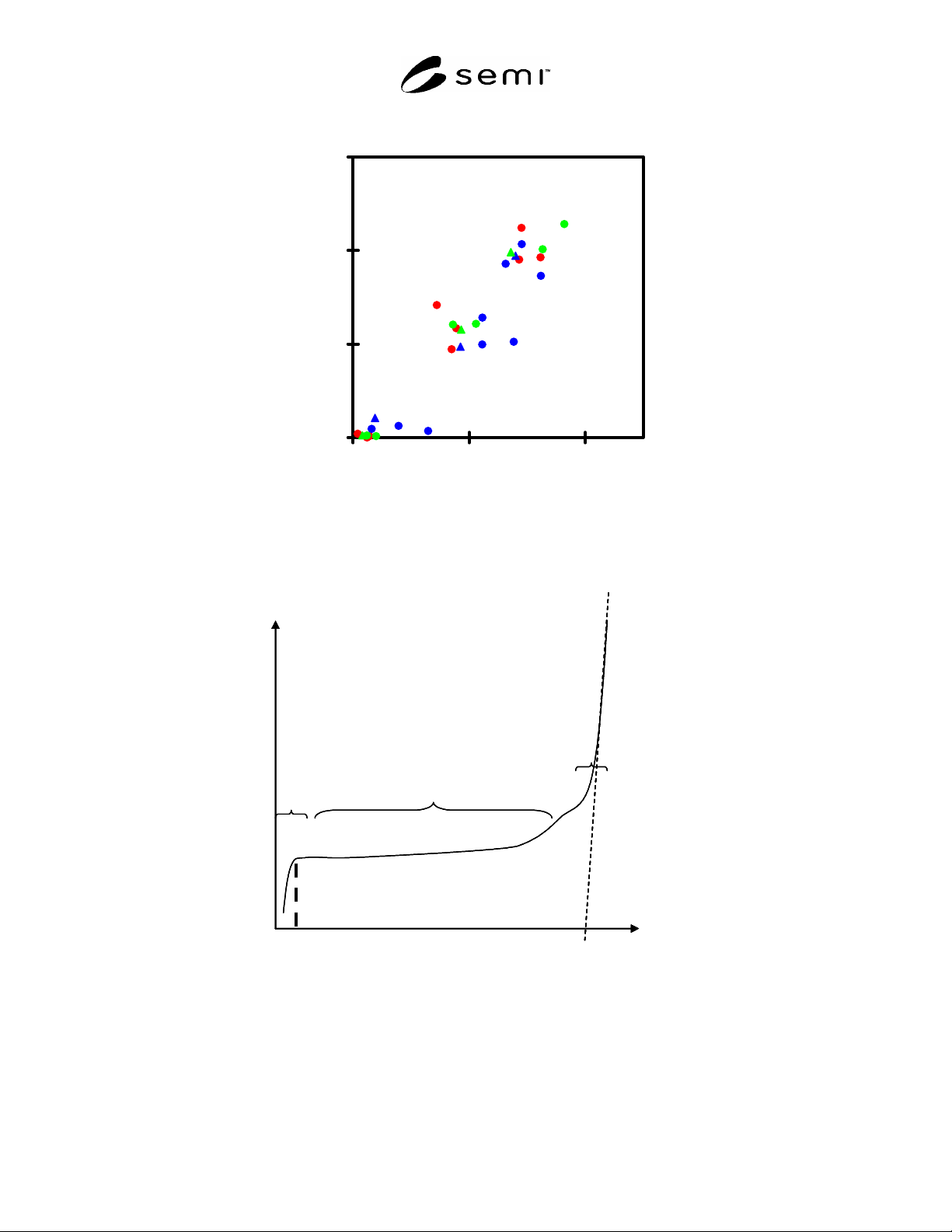
R1-2.1.1 A correlation between TZDB and TDDB is shown in Figure RI-1. This result is based on round robin.
This figure is shown by defect densities of the TZDB and TDDB measurements. The defect densities of TDDB are
generally higher than those of TZDB. This result is shown that the sensitivity to dielectric breakdown defect of
TDDB measurement is higher than that of TZDB measurement.
R1-3 Classification of Breakdown mode
R1-3.1 In Figure RI-2, a typical cumulative failure fraction is shown as a function of charge injected before
breakdown. Such a plot is called the TDDB Weibull plot. In the Weibull plot of the TDDB result, the breakdown
events are categorized into the following three modes.
R1-3.2 A-A Mode — Initial Breakdown Failure
R1-3.2.1 Integrity of the oxide films in this mode is very low. There are COPs or oxygen precipitates other than
particles, alkaline and metallic contamination at the Si surface of the MOS capacitors in this category. Classification
of this mode with the following A-B mode is performed at a small amount of injected charge, Q
a
, as illustrated in
Fig RI-2. For example, the classification charge, Q
a
, was 0.01C/cm
2
in this round robin. This failure is caused by
defects generated during formation of the gate oxide such as pinholes and also by crystal defects such as COPs.
That is, this failure corresponds to the A mode and partial B mode failure of TZDB.
R1-3.3 A-B Mode — Intermediate Breakdown Failure
R1-3.3.1 This failure occurs in the intermediate time range from initial breakdown failure to wearout breakdown.
This failure is caused by extrinsic defects. This failure corresponds to the B mode and partial C-mode failure of
TZDB.
R1-3.4 W Mode — Wearout Breakdown
R1-3.4.1 This breakdown is also called intrinsic breakdown or wearout breakdown, and related to the intrinsic
lifetime of oxide films. The failure fraction steeply increases as shown in Figure R1-2. The measurement of this
breakdown should be performed carefully because the result depends on measurement conditions.
R1-3.4.2 Classification of the accidental and wearout modes, that is, the A-B and W modes, is far from easy
because the W mode gradually shifts toward the A-B mode as shown in Figures R1-3, R1-5 and R1-6. It is
statistically supported that the Weibull plot is straight in the W mode region. The regression straight line has the
correlation coefficient higher than 0.9 with the experimental data. When the A-B mode breakdown events are added
to the breakdown data, a correlation coefficient of the data and its straight line approximation decreases. This
characteristic to determine the classification of the accidental and wearout modes can be used. In this round robin,
the classification of the injected charge density, Q
w
, was determined as follows. A regression straight line in the
injected charge density range of higher than Q
w
was obtained by the least square method. The recommended
correlation coefficient is higher than 0.95. Q
w
is 2C/cm
2
in Figure R1-4. In a different manner, the cross point of
two regression straight lines in the A-B and W mode breakdown ranges was read as Q
w
.

SEMI M60-0305 © SEMI 2005 15
R1-4 Dependence of Stress Current Density
R1-4.1 In this TDDB measurement, the stress electric field was applied so as to keep the oxide leakage current
constant. The applied voltage was monitored at the constant time interval. A stress current of 0.001 A/cm
2
or less
leads to uselessly long measurement time.
R1-4.2 On the other hand, too high a current density leads to nonuniform application of the stress voltage to the
gate oxide. That is, the reliability of the measurement is reduced.
R1-4.3 In this round robin, the applied stress condition is shown in Table R1-1.
R1-4.4 The Weibull plot obtained in this round robin is shown in Figure R1-5. The Q
bd
values and the accidental
failure rates are shown in Table R1-2. The Q
bd
clearly depended on the stress current in the stress range of this
round robin. The Q
bd
decreased with increasing stress current density, though the difference of the failure rates is
slight. The failure rates in this result were defined by the sum of the accidental initial and intermediate modes in
Figure R1-2. The classification between intermediate (A-B mode) and wearout (W mode) breakdowns was
performed at the injected charge density of 2C/cm
2
.
R1-4.5 The total accidental failure rates, that is, the sum of the A-A and A-B modes, were not influenced by the
current density in this round robin condition. Therefore, the recommended stress current density range is from 0.1 to
0.01A/cm
2
.
R1-5 Dependence of Measurement Temperature
R1-5.1 On the other hand, in this TDDB measurement, the stress temperature is an important parameter. The Q
bd
depended on the stress temperature. Too high a temperature degrades the measurement system. In the stress
temperature range of room temperature to 125ºC, systematic TDDB data were obtained. The recommended stress
temperature is 125ºC or less.
R1-5.2 The stress conditions in this round robin are shown in Table R1-1. In this table, the accidental failure rate
was defined by the sum of the initial and intermediate breakdowns in Figure R1-2. In this case, the classifications of
the A-B and W modes were defined as follows:
125ºC–2C/cm
2
85ºC–5C/cm
2
25ºC (r.t.)–10C/cm
2
R1-5.3 The Q
bd
depended on the stress temperature in this round robin condition. However, the sum of the
accidental A-A and A-B breakdown modes was independent of stress temperature. Therefore, taking into
consideration the above practical factors, the reasonable stress temperature range is from room temperature to
125ºC.
SEMI M60-0305 © SEMI 2005 16
0
5
10
15
01020
TDDB defect density(cm-2)
TZDB B-mode defect density(cm-2)
Figure R1-1
Correlation of Defect Densities of TZDB and TDDB Measurements
Qbd
Weibull
I
n
i
t
i
a
l
B
r
e
a
k
d
o
w
n
We
a
ro
u
t
B
r
e
a
k
d
o
w
n
I
n
t
e
r
m
e
d
i
a
t
e
B
r
e
a
k
d
o
w
n
Q
a
log Q
BD
Qbd
Weibull
I
n
i
t
i
a
l
B
r
e
a
k
d
o
w
n
We
a
ro
u
t
B
r
e
a
k
d
o
w
n
I
n
t
e
r
m
e
d
i
a
t
e
B
r
e
a
k
d
o
w
n
Q
a
Qbd
Weibull
I
n
i
t
i
a
l
B
r
e
a
k
d
o
w
n
We
a
ro
u
t
B
r
e
a
k
d
o
w
n
I
n
t
e
r
m
e
d
i
a
t
e
B
r
e
a
k
d
o
w
n
Q
a
log Q
BD
Figure R1-2
Classification of TDDB Breakdown Mode