semi合集-English.pdf - 第547页
SEMI E78-1102 © SEMI 1998, 2002 5 In Ground Electrometer Faraday Cup Isolated Inner Cup Shielding Outer Cup Figure 1 Faraday Cup Charge Me asurement 7.1.1 The relat ionship bet ween ESD simulator te sting for product da …

SEMI E78-1102 © SEMI 1998, 2002 4
Precise measurements will be difficult as the presence
of the measuring instrument changes the field
characteristics and may overstate the actual level of
electrostatic field. This is shown in Section 7, Figure 3.
SEMI E43 describes measurement techniques using an
electrostatic fieldmeter.
6.3.3 Electrostatic deposition velocity depends only on
electric field, particle size and particle charge.
However, the concentration of particles deposited on a
surface also depends on the particle concentration in the
equipment area and the length of the exposure time
during which particle deposition occurs. Mechanisms
other than electrostatic deposition, such as gravitational
settling and diffusion, can also contribute to particle
deposition. The concentration of particles deposited by
these non-electrostatic mechanisms will also vary with
particle concentration in the equipment ambient and
exposure time.
6.3.4 Comparisons of the electrostatic deposition
velocity with the deposition velocities associated with
these other deposition mechanisms is the key for
determining threshold values of allowed electrostatic
field from the viewpoint of particle deposition. Such
comparisons are the basis for estimating the allowed
values of electrostatic field presented in Appendix A1-
2.2 and Related Information R1-2. Users and equipment
manufacturers should determine and agree on ambient
particle sizes and concentrations, and product exposure
times.
6.4 Equipment ESD
6.4.1 Equipment ESD immunity is being addressed in
general through a number of international standards
including IEC 61000-4-2 and BS EN 61000-6-2 for
European CE compliance. Measurements are made
using an ESD simulator which is described in these
standards.
6.4.2 The ESD simulator is used to create both a direct
discharge to the surface of the equipment and an air
discharge to a surface 10 cm (4 inches) away from the
equipment. The ESD simulator charges a 150 picofarad
capacitor (C) to a known voltage (V) and then
discharges it to produce a standardized discharge
waveform. Knowing the voltage and capacitance
involved in this test means the total charge can be
calculated by the equation q = CV. For example, a 4000
volt discharge (IEC 61000-4-2 test level) transfers a
charge, q = 600 nanocoulombs.
6.4.3 The value of the capacitor (C) in the ESD
simulator is specified in the international standards. It
should not be assumed that a different value of
capacitance and voltage that produce the same charge
transfer of 600 nanocoulombs would have the same
affect on a specific piece of equipment. Discharge
currents will vary with the impedance of the discharge
path and with the voltage. It is, however, impractical to
test all possible combinations. For the purposes of this
guide, the parameters of the ESD simulator specified in
the standards for equipment ESD immunity will be
used.
6.4.4 For true ESD immunity, an ESD event in
equipment must not disturb either the equipment it
occurs in, or another nearby piece of equipment. Charge
on product or carriers transferred from one piece of
equipment must not disturb the operation of subsequent
equipment. It will be a systems issue to make sure that
all equipment in a facility meets the required ESD
immunity standards.
6.4.5 The range of reactions in equipment to an ESD
event runs from transient errors that are automatically
corrected, to hard errors that cannot be corrected
without manual intervention or damage the equipment.
While small numbers of transient errors may be
acceptable from the point of view of equipment
operation, they may still cause unacceptable product
losses.
6.4.6 The user and manufacturer must determine with
an ESD simulator what levels of ESD cause equipment
interruptions. The user must determine if any of these
equipment interruptions caused by ESD are acceptable.
6.4.7 In setting a level to provide ESD immunity for
an individual piece of equipment from static charge on
products and carriers, the charge on these items should
be kept below the levels determined by ESD simulator
testing.
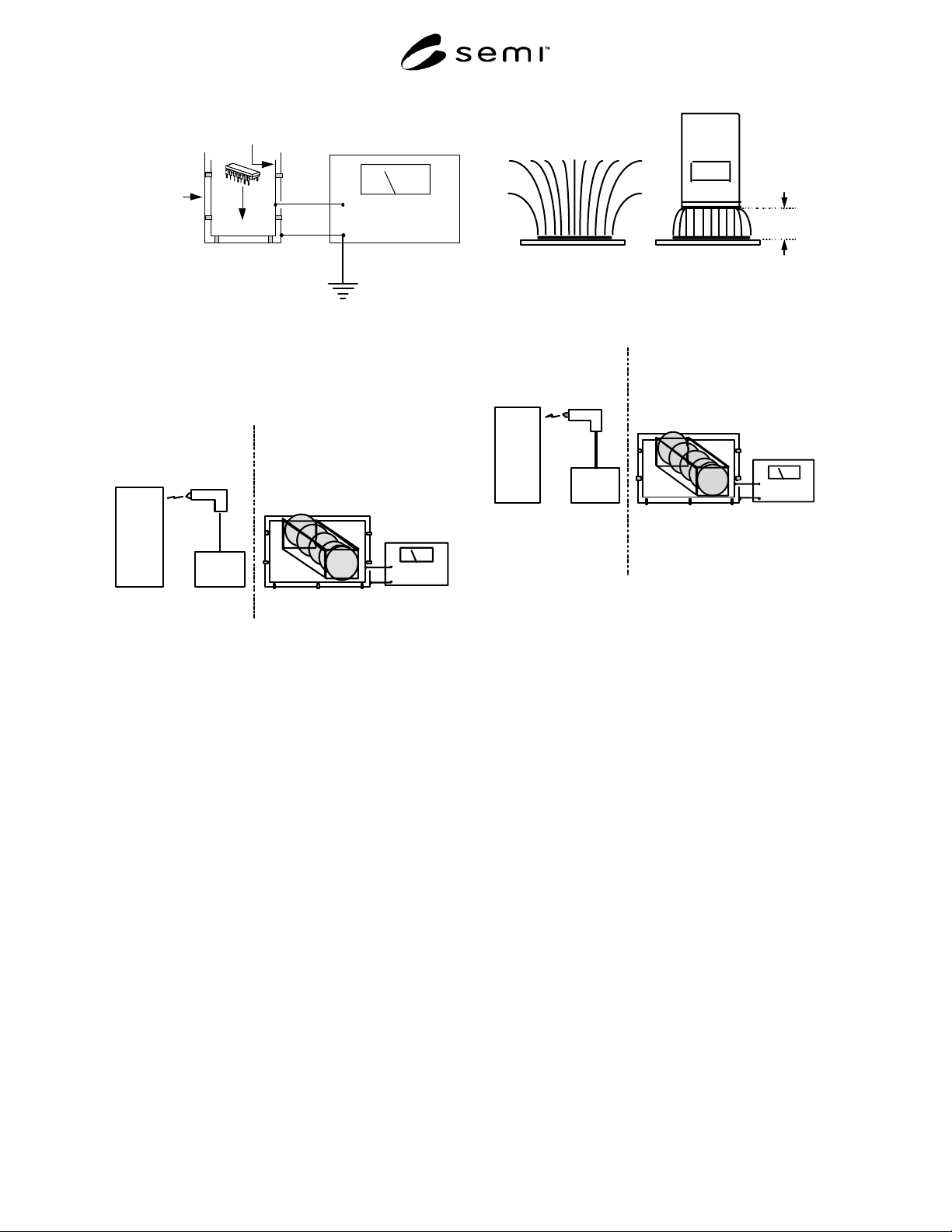
6.4.8 The Faraday Cup measurement can be used for
this purpose. If equipment has been tested for ESD
immunity and passes a 4000 volt test, then total charge
on product and carriers leaving this equipment should
be kept below 600 nanocoulombs. Any product
transferred at this level should not be handled by other
equipment with a lower ESD immunity. A possible
implementation of this test method is shown in Section
7, Figure 4.
7 Apparatus
7.1 ESD Damage — The apparatus for determining the
ESD damage thresholds for products will depend on the
test methods used. See Section 4 for additional
information. For measuring the charge generated on
product, reticles, or carriers, the Faraday Cup test
method is shown in Figure 1.
SEMI E78-1102 © SEMI 1998, 2002 5
In
Ground
Electrometer
Faraday
Cup
Isolated
Inner Cup
Shielding
Outer Cup
Figure 1
Faraday Cup Charge Measurement
7.1.1 The relationship between ESD simulator testing
for product damage and charge measurements using the
Faraday cup is shown in Figure 2.
1000
VOLTS
DEVICE
UNDER
TEST
ESD
SIMULATOR
HBM, MM, CDM
100 NANOCOULOMB
DISCHARGE IMMUNITY
FARADAY
CUP
WAFER OR RETICLE CASSETTES
WAFERS, RETICLES, OR ICs
LESS THAN 100 NANOCOULOMB
ALLOWABLE CHARGE LEVEL
WAFER
RETICLE
IC
Figure 2
ESD Damage Testing
7.2 The instrument used for making electrostatic field
measurements is known as an electrostatic fieldmeter.
Instructions concerning its use should be obtained from
the instrument manufacturer and SEMI E43. The
measurement configuration shown in Figure 3
illustrates the effect of the instrument on the
measurement. In most cases the presence of the
fieldmeter will increase both the flux from the charged
surface and the divergence of the electric field lines.
The fieldmeter will generally indicate a higher value of
electric field than would be present without the
fieldmeter.
7.3 The instrumentation and test methods for
determining the ESD sensitivity of equipment are
described by IEC 6100-4-2 or other acceptable test
methods. The amount of static charge determined by
this test method is to be compared with the charge
measured on products and carriers with the Faraday
Cup test method. Figure 4 illustrates the two methods.
1999
+ + + + + + + + + + + + + + + +
2.54 cm
(1 inch)
Electrostatic
Fieldmeter
(volts/cm)
+ + + + + + + + + + + + + + + +
Charged
Surface
Electric Field Lines
Charged
Surface
Figure 3
Electrostatic Field Measurement
4000
V
OLTS
EQUIPMENT
UNDER
TEST
ESD
SIMULATOR
600 NANOCOULOMB
DISCHARGE IMMUNITY
FARADAY
CUP
WAFER CASSETTE
A
ND WAFERS
LESS THAN 600 NANOCOULOMB
A
LLOWABLE CHARGE LEVEL
Figure 4
ESD Immunity Testing
8 Safety Precautions
8.1 Personnel — Static charges can create safety
hazards during some semiconductor production
processes. ESA or ESD events that result in the
jamming or breakage of product in high speed
equipment may create a personnel hazard. ESD events
that produce sparks must be prevented in areas that use
flammable or explosive chemicals or gases. ESD events
to personnel are usually not harmful, but they may
result in an unwanted reflex, or “startle” reaction. This
reflex may create a personnel hazard, particularly in the
vicinity of moving equipment or where caustic
chemicals are in use. It may be necessary to use
additional static charge control methods, beyond those
used inside the equipment, to minimize these personnel
hazards.
8.2 Measurement Safety — Users should exercise
caution while making static charge measurements in the
vicinity of moving parts of production equipment, or in
areas where static potentials on ungrounded conductors
may exceed 30,000 volts. Refer to SEMI E43 for
additional measurement safety considerations.

SEMI E78-1102 © SEMI 1998, 2002 6
9 Test Specimen
9.1 The user and equipment manufacturer will need to
agree on:
• The type(s) of testing to be performed,
• Who will do the testing,
• The number and type of test samples,
• The number of measurements, and
• Acceptable test results.
9.2 The operating history of the equipment prior to, or
during testing (e.g., warm-up time, type of carrier,
number of products processed, operating speed), and all
appropriate environmental conditions (e.g.,
temperature, humidity, airflow) should be agreed upon
and documented.
10 Preparation of Apparatus
10.1 Depending on the type of testing to be done,
consult the appropriate testing document for apparatus
preparation. See Sections 4 and 16 for additional
information.
11 Calibration and Standardization
11.1 Depending on the type of testing to be done,
consult the appropriate testing document for apparatus
calibration and verification. See Sections 4 and 16 for
additional information.
12 Procedures
12.1 Refer to Sections 6 and 7 and the appropriate test
methods of Sections 4 and 16.
12.2 ESD Damage
12.2.1 Users shall establish product damage thresholds
for their products. Measurement methods for integrated
circuits are described in the documents contained in
Sections 4 and 16. Appropriate measurement methods
for ESD damage to wafers, reticles, and other items
may be adapted from the instrumentation used in these
test methods. Appendix A1-2.1 and Related
Information R1-1 contain additional information to
select an appropriate sensitivity level to reduce ESD
damage.
12.2.2 Measurement of ESD damage thresholds are
made in units of nanocoulombs (nC = 10
-9
coulombs).
12.2.3 The Faraday Cup method is used to determine
the static charge levels on products, product carriers
and equipment parts. Each item shall be transported to
the Faraday cup in a way that does not alter its charge
level. Consult the measurement equipment
manufacturer’s instructions for recommendations on
how to achieve this.
12.2.4 Measurements should be made of products,
carriers, and materials in the equipment input/exit ports
after significant amounts of product have been handled
under normal manufacturing conditions. Measurements
should be made of products and their carriers after they
have undergone normal processing in the equipment
under test. Typically five measurements of products
and/or carriers should be sufficient to demonstrate
compliance with the selected Sensitivity Level.
12.2.5 Measurements should be made on each of three
successive days after equipment has stabilized in its
normal operating mode (e.g., after two hours).
12.3 Particle Attraction
12.3.1 Users should work with equipment
manufacturers to determine ambient particle levels and
product exposure times during processing. Appendix
A1-2.2 and Related Information R1-2 contain
information to select an appropriate Sensitivity Level to
reduce electrostatic attraction of particles.
12.3.2 Electrostatic field measurements on products,
product carriers, and equipment surfaces should be
made in at least three different locations on any item.
Locations should be separated by approximately three
times the distance between the measuring instrument
and the measurement location. For most electrostatic
fieldmeters measuring at 25.4 mm (1 inch), the
measurement locations will be 76.2 mm (3 inches)
apart. Refer to SEMI E43 for additional measurement
considerations. Measurements of electrostatic field are
expressed in volts/cm or volts/inch.
12.3.3 Measurements should be made on products,
carriers, and materials in the equipment input/exit ports
after significant amounts of product have been handled
under normal manufacturing conditions. Measurements
should be made of products and their carriers after they
have undergone normal processing in the equipment
under test. Typically five measurements of products
and/or carriers should be sufficient to demonstrate
compliance with the selected Sensitivity Level.
12.3.4 Measurements should be made on each of three
successive days after equipment has stabilized in its
normal operating mode (e.g., after two hours).
12.4 Equipment ESD
12.4.1 Equipment manufacturers should determine the
effects of ESD on their equipment using an ESD
Simulator and the appropriate test methods (IEC 6100-
4-2 or others). Users should agree on the types of
equipment interrupts that are acceptable (if any).
Appendix A1-2.3 and Related Information R1-3 contain