semi合集-English.pdf - 第5490页
SEMI P5-0704 © SEMI 1986, 2004 1 SEMI P5-0704 SPECIFICATION FOR PELLICLES This specification was technically approved by the Global Mi cropatterning Com mittee and is the direct responsibility of the North American Micro…
SEMI P4-92 © SEMI 1983, 1999 6
APPENDIX 1
NOTE: This appendix was approved as an official part
of SEMI P4 by full letter ballot procedure.
Hard Surface Photomask Glass Properties
Quartz Properties
Property
Ultra Low Thermal Expansion Ulte
Modulus of Elasticity
6.7-7.4 × 10
3
Kg/mm
2
Poisson' s Ratio 0.18-0.19
(1)
Specific Gravity 2.18-2.20 g/cm
3
Index of Refraction 1.46
NOTE: These properties are not absolute requirements. For
more specific information, contact your individual supplier.
NOTICE: These standards do not purport to address
safety issues, if any, associated with their use. It is the
responsibility of the user of these standards to establish
appropriate safety and health practices and determine
the applicability of regulatory limitations prior to use.
SEMI makes no warranties or representations as to the
suitability of the standards set forth herein for any
particular application. The determination of the
suitability of the standard is solely the responsibility of
the user. Users are cautioned to refer to manufacturer' s
instructions, product labels, product data sheets, and
other relevant literature respecting any materials
mentioned herein. These standards are subject to
change without notice.
The user' s attention is called to the possibility that
compliance with this standard may require use of
copyrighted material or of an invention covered by
patent rights. By publication of this standard, SEMI
takes no position respecting the validity of any patent
rights or copyrights asserted in connection with any
item mentioned in this standard. Users of this standard
are expressly advised that determination of any such
patent rights or copyrights, and the risk of infringement
of such rights, are entirely their own responsibility.
Copyright by SEMI® (Semiconductor Equipment and Materials
International), 3081 Zanker Road, San Jose, CA 95134. Reproduction o
f
the contents in whole or in part is forbidden without express written
consent of SEMI.

SEMI P5-0704 © SEMI 1986, 2004 1
SEMI P5-0704
SPECIFICATION FOR PELLICLES
This specification was technically approved by the Global Micropatterning Committee and is the direct
responsibility of the North American Microlithography Committee. Current edition approved by the North
American Regional Standards Committee on April 22, 2004. Initially available at www.semi.org June 2004;
to be published July 2004. Originally published in 1986; previously published in 1994.
NOTICE: This document was completely rewritten in
2004 to combine SEMI P5, SEMI P5.1, and SEMI
P5.2.
1 Preface
1.1 This specification covers requirements for pellicles
used on photomasks or reticles in photolithographic
exposure systems. This specification covers pellicles
for use in either broadband, polychromatic or
monochromatic exposure systems.
NOTICE: This standard does not purport to address
safety issues, if any, associated with its use. It is the
responsibility of the users of this standard to establish
appropriate safety and health practices and determine
the applicability of regulatory or other limitations prior
to use.
2 Referenced Standards
None.
3 Terminology
3.1 Additional terms are listed for information only in
the glossary, SEMI Compilation of Terms.
3.2 Selected Definitions
3.2.1 pellicle — a thin, optically transparent film,
typically of a polymer, attached to and supported by a
frame, and attached to a photomask (or reticle). Its
purpose is to seal out contaminants and reduce printed
defects caused by contamination in the image plane of
an optical exposure system with a minimum decrease in
the quality of optical transmission.
3.2.2 film adhesive — adhesive between frame and
film.
3.2.3 frame adhesive — adhesive between frame and
photomask.
3.2.4 mechanical strength — the physical condition a
pellicle must meet to withstand a specified force from a
blow-off gun without suffering any damage to the film
due to stretching or breakage.
3.2.5 film defects — inconsistencies in the integrity and
planarity of the film, including particles, pinholes,
scratches, dirt, and a minute quantity of solid.
3.2.5.1 particle — materials that can be distinguished
from the film whether on the film surface or embedded
in the film.
3.2.5.2 dirt — fingerprint; mark left behind after
operator handling; stain from liquid.
3.2.5.3 pinhole — a small opening completely through
a polymer film.
3.2.5.4 scratch — long, narrow, shallow groove or cut
below the established plane of the surface.
3.2.6 adhesive stringer — Any detectable protrusion
from the edge of the adhesive.
3.2.7 light resistance – Minimum cumulative exposure
energy a pellicle can withstand without (or within
specified) change in performance.
4 Ordering Information
4.1 Purchase orders of pellicles furnished to this
specification shall include the following:
4.1.1 Shape, Size, and Standoff of Pellicle — The
information relating to the Shape, Size, and Standoff of
a pellicle may be combined into a single frame part
number, or must be provided separately. For any given
model of stepper or mask aligner the manufacturer will
specify a recommended shape, size and standoff. The
user for inter-operability reasons may specify
alternative values.
4.1.1.1 Shape — This is determined by agreement
between the user and the supplier.
4.1.1.2 Size — This is determined by agreement
between the user and the supplier. Any expression of
tolerance is as follows:
Outer edge tolerance: +0, -x
Inner edge tolerance: +x, -0
4.1.1.3 Standoff — This is determined by agreement
between the user and the supplier. Any expression of
tolerance is +0, -x.
4.1.2 Film Characteristics
4.1.2.1 Type — An anti-reflective (AR) coating may be
applied to either the inside or outside surfaces of the
polymer film. Which surfaces, if any, require the
SEMI P5-0704 © SEMI 1986, 2004 2
presence of an AR-coating is determined by agreement
between the user and the supplier.
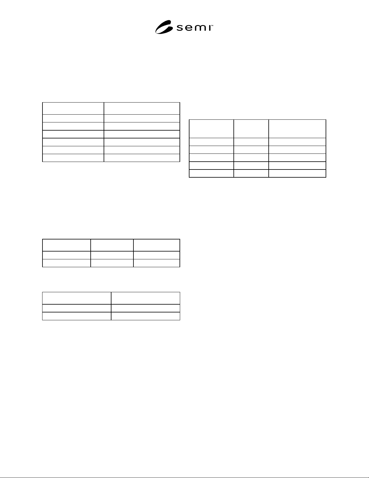
4.1.2.2 Exposure Range or Wavelength — The
wavelength(s) of the exposure system(s) must be
specified. Table 1 shows the typical exposure
wavelengths.
Table 1 Typical Exposure Wavelengths
Terminology Exposure Wavelength(s)
Broadband 360 nm–440 nm
g-line 436 nm
h-line 405 nm
i-line 365 nm
DUV 248 nm
DUV 193 193 nm
4.1.2.3 Optical Transmission — There are two types of
optical transmission depending on the film type. These
are measured at an incident angle of 90° from the
surface of the pellicle at the specified wavelength(s).
The acceptable values are specified in Tables 2 and 3.
The Minimum Transmission given in Table 3 apply to
all wavelengths the film is specified for.
Table 2 Transmission for Broadband Exposure
Systems
Type Average Minimum
AR-Coated ≥ 98 % 96%
Non-AR-Coated ≥ 91 % 82%
Table 3 Transmission for Monochromatic Exposure
Systems
Type Minimum
AR Coated 99%
Non AR Coated 98%
4.1.2.4 Thickness — This is determined by agreement
between user and supplier. The default thickness
tolerance is ± 0.1 µm maximum for Broadband
Exposure Systems and ± 0.05 µm maximum in all other
cases.
4.1.2.5 Mechanical Strength — The pellicle film must
withstand air blow within ranges shown below:
Air pressure: ≤ 2.1 kgf/cm
2
(at input of the air blow
gun).
Nozzle diameter of the air blow gun: ≤ 2 mm.
Distance between the nozzle tip and the film: ≥ 25 mm.
4.1.2.6 Defect Limits — Maximum defect limits are
determined by agreement between the user and the
supplier. These are based on the pellicle standoff, the
numerical aperture and exposure wavelength of the
given type of exposure system, and a typical
specification is given in Table 4. For broadband
exposure systems a typical value of size would be 45
µm, and for monochromatic exposure systems the size
will be significantly smaller.
Table 4 Maximum Defect Limits
Characteristics
Max. No.
Allowable
Size Counted for Max.
No. Allowable
Non-removable
Particles None > size µm
Pinholes None >limit of detection
Scratches None Width > size µm
Dirt None >limit of detection
4.2 In addition, the following items may also be
specified:
4.2.1 Frame Material or Type
4.2.2 Frame Finishing or Coating
4.2.3 Frame Shape, Size and Height
4.2.4 Frame Adhesive Material or Type.
4.2.5 Frame Adhesive Thickness and Width.
4.2.6 Film Adhesive Material or Type
4.2.7 Film Adhesive Thickness and Width.
4.2.8 Film Thickness Uniformity.
4.2.9 Pellicle Vent Mechanism, e.g. vent hole.
4.2.10 Frame inner-wall adhesive.
4.3 If two pellicles will be attached to a photomask
then each pellicle should be independently specified.
For thicker photomask substrates a pellicle is only
attached to the patterned side of the photomask. For
thinner photomask substrates a pellicle is normally
attached to both the patterned and glass sides of the
photomask.
5 Requirements
5.1 Film Adhesive — Film must be sealed on the entire
top of the frame. Seal with a minimum of 50% of the
frame width at any location.
5.2 Frame Adhesive — Frame adhesive must be
continuous and allow no gaps larger than the Defect
Size Limit between pellicle frame and adhesive, and
between adhesive and photomask after attachment. No
part of the frame adhesive may extend beyond the