semi合集-English.pdf - 第5918页
SEMI P39-0304 E2 © SEMI 2004 21 27 PATH Record 27.1 A PATH reco rd represents an arbitrary path f igure, which may be thought of as a polyline with f inite width. It has the following format: ‘22’ path-info - byte [ l ay…
SEMI P39-0304
E2
© SEMI 2004 20
24.7 EXCEPTION HANDLING — Use of a reference-number for which there is no corresponding
TEXTSTRING record within the same OASIS file should be treated as a fatal error. Implicit use of modal variables
textlayer or texttype when they are in the undefined state should be treated as a fatal error.
25 RECTANGLE Record
25.1 A RECTANGLE record represents a rectangular figure whose edges are parallel to the x- and y-axes. It has
the following format:
‘20’ rectangle-info-byte [ layer-number ] [ datatype-number ] [ width ] [ height ] [ x ] [ y ] [ repetition ]
25.2 The rectangle-info-byte contains the bit pattern ‘SWHXYRDL’.
25.3 R is 1 if repetition is present. L is 1 if layer-number is present. D is 1 if datatype-number is present. Both
layer-number and datatype-number are unsigned-integers. When layer-number and/or datatype-number are
unspecified, they assume the value of modal variables layer and datatype, respectively. W is 1 if width is present.
H is 1 if height is present. Both width and height are unsigned-integers. When width and/or height are
unspecified, they assume the value of modal variables geometry-w and geometry-h, respectively.
25.4 S is 1 if the rectangle is a square. In this case, H must be 0, and width, if present, is used for both dimensions
of the rectangle. When width is unspecified, the value of modal variable geometry-w is used instead.
25.5 x and y
are signed-integer coordinates representing either the absolute or the relative (x,y) location of the
lower-left corner of the rectangle. X is 1 if x is present, and Y is 1 if y is present. When either x or y is unspecified,
the value of modal variable geometry-x or geometry-y, respectively, is used instead. Refer to Section 21 on page 17
for a discussion of how absolute and relative modes affect the interpretation of x and y.
25.6 Each successive RECTANGLE record updates all rectangle-related modal variables. (When S = 1, both
geometry-w and geometry-h are set to the rectangle’s width.)
25.7 EXCEPTION HANDLING
— Implicit use of modal variables geometry-w, geometry-h, layer, or datatype
when they are in the undefined state should be treated as a fatal error. When S = 1, H = 1 should be treated as a fatal
error. The interpretation of zero-area RECTANGLEs is application-dependent.
26 POLYGON Record
26.1 A POLYGON record represents an arbitrary polygon figure. It has the following format:
‘21’ polygon-info-byte [ layer-number ] [ datatype-number ] [ point-list ] [ x ] [ y ] [ repetition ]
26.2 The polygon-info-byte contains the bit pattern ‘00PXYRDL’.
26.3 x and y are signed-integer coordinates representing either the absolute or the relative (x,y) location of the
initial vertex of the polygon. X is 1 if x is present, and Y is 1 if y is present. When either x or y is unspecified, the
value of modal variable geometry-x or geometry-y, respectively, is used instead. Refer to Section 21 on page 17 for a
discussion of how absolute and relative modes affect the interpretation of x and y.
26.4 R is 1 if repetition is present. L is 1 if layer-number is present. D is 1 if datatype-number is present. Both
layer-number and datatype-number are unsigned-integers. When layer-number and/or datatype-number are
unspecified, they assume the value of modal variables layer and datatype, respectively.
26.5 P
is 1 if point-list is present. Otherwise, the value of modal variable polygon-point-list is used. The format of
point-lists is defined in Section 7.7 on page 9.
26.6 Each successive POLYGON record updates all polygon-related modal variables.
26.7 EXCEPTION HANDLING
— Polygons with fewer than three vertices should be treated as fatal errors. Implicit
use of modal variables polygon-point-list, layer, or datatype when they are in the undefined state should be treated
as a fatal error. The interpretation of self-intersecting polygons, reentrant polygons, and polygons with zero-area
regions is application-dependent.
SEMI P39-0304
E2
© SEMI 2004 21
27 PATH Record
27.1 A PATH record represents an arbitrary path figure, which may be thought of as a polyline with finite width. It
has the following format:
‘22’ path-info-byte [ layer-number ] [ datatype-number ] [ half-width ]
[ extension-scheme [ start-extension] [ end-extension ] ] [ point-list ] [ x ] [ y ] [ repetition ]
27.2 The path-info-byte contains the bit pattern ‘EWPXYRDL’.
27.3 x and y are signed-integer coordinates representing either the absolute or the relative (x,y) location of the
initial vertex of the path centerline. X is 1 if x is present, and Y is 1 if y is present. When either x or y is unspecified,
the value of modal variable geometry-x or geometry-y, respectively, is used instead. Refer to Section 21 on page 17
for a discussion of how absolute and relative modes affect the interpretation of x and y.
27.4 R is 1 if repetition is present. L is 1 if layer-number is present. D is 1 if datatype-number is present. Both
layer-number and datatype-number are unsigned-integers. When layer-number and/or datatype-number are
unspecified, they assume the value of modal variables layer and datatype, respectively.
27.5 P is 1 if point-list is present. Otherwise, the value of modal variable path-point-list is used. The format of
point-lists is defined in Section 7.7 on page 9.
27.6 W
is 1 if half-width (an unsigned-integer) is present; if absent, the half-width value assumes the value of
modal variable path-halfwidth. The path is formed by expanding the centerline (represented by line segments
connecting the points) by the half-width value to each side.
27.7 E is 1 if extension-scheme is present. Otherwise, extension-scheme, start-extension, and end-extension are
absent, and the values of modal variables path-start-extension, and path-end-extension are used instead.
27.8 When present, extension-scheme (an unsigned-integer) contains bit pattern ‘0000SSEE’. The SS bits govern
the path starting extension, and the EE bits govern the path ending extension. Both start-extension (present only
when SS = ‘11’) and end-extension (present only when EE = ‘11’) are signed-integers, as in GDSII Stream, with
positive values causing the path to extend beyond its starting and/or ending vertices, and negative values causing the
path to retract from its starting and/or ending vertices.
Table 15 Path Extension Schemes
SS Bits Description
00 Use path-start-extension modal variable
01 Use flush (zero-length) extension at starting vertex
10 Use path-halfwidth extension at starting vertex
11 Use explicit start-extension at starting vertex
EE Bits
00 Use path-end-extension modal variable
01 Use flush (zero-length) extension at ending vertex
10 Use path-halfwidth extension at ending vertex
11 Use explicit end-extension at ending vertex
27.9 Each successive PATH record updates all path-related modal variables.
27.10 Various types of degenerate paths, where the half-width = 0, the path traces back on itself, an extension is
negative with magnitude greater than its segment length, etc. are not prohibited; their interpretation is application-
dependent. The path expansion scheme used at the path’s interior vertices or “joints” is also application-dependent.
27.11 EXCEPTION HANDLING
— Implicit use of modal variables path-halfwidth, path-point-list, path-start-
extension, path-end-extension, layer, or datatype when they are in the undefined state should be treated as a fatal
error.
SEMI P39-0304
E2
© SEMI 2004 22
28 TRAPEZOID Record
28.1 A TRAPEZOID record represents a trapezoid figure (a polygon with four vertices having at least two
opposite sides parallel and parallel to either the x- or the y-axis). It has the following format:
‘23’ trap-info-byte [ layer-number ] [ datatype-number ]
[ width ] [ height ] delta-a delta-b [ x ] [ y ] [ repetition ]
‘24’ trap-info-byte [ layer-number ] [ datatype-number ]
[ width ] [ height ] delta-a [ x ] [ y ] [ repetition ]
‘25’ trap-info-byte [ layer-number ] [ datatype-number ]
[ width ] [ height ] delta-b [ x ] [ y ] [ repetition ]
28.2 The trap-info-byte contains bit pattern ‘OWHXYRDL’.
28.3 R is 1 if repetition is present. L is 1 if layer-number is present. D is 1 if datatype-number is present. Both
layer-number and datatype-number are unsigned-integers. When layer-number and/or datatype-number are
unspecified, they assume the value of modal variables layer and datatype, respectively. W is 1 if width is present.
H is 1 if height is present. Width and height are unsigned-integers which describe the overall dimensions of the
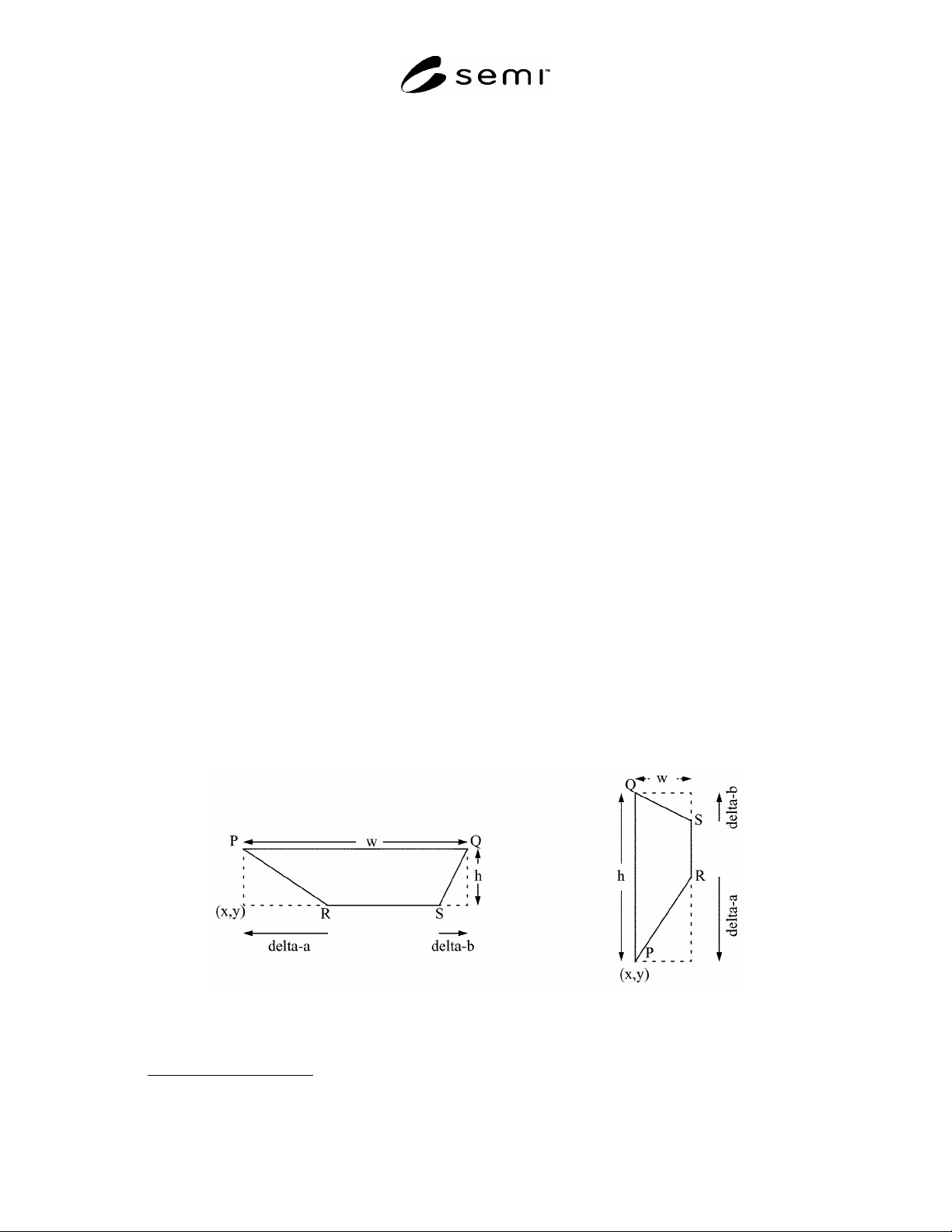
bounding box of the trapezoid as shown in Figure 7 on page 22. When width and/or height are unspecified, they
assume the value of modal variables geometry-w and geometry-h, respectively.
28.4 x and y are signed-integer coordinates representing either the absolute or the relative (x,y) location of the
lower-left corner of the trapezoid’s bounding box. X is 1 if x is present, and Y
is 1 if y is present. When either x or y
is unspecified, the value of modal variable geometry-x or geometry-y, respectively, is used instead. Refer to Section
21 on page 17 for a discussion of how absolute and relative modes affect the interpretation of x and y.
28.5 delta-a and delta-b are 1-deltas, and are both present in record type ‘23’. In record type ‘24’ delta-b is
assumed to be 0 and is omitted, and in record type ‘25’ delta-a is assumed to be 0 and is omitted.
28.6 O is 0 if the trapezoid is horizontally-oriented, with top (PQ) and bottom (RS) sides parallel to the x-axis. In
this case, delta-a represents (x
P
- x
R
) and delta-b represents (x
Q
- x
S
).
28.7 O is 1 if the trapezoid is vertically-oriented, with left (PQ) and right (RS) sides parallel to the y-axis. In this
case, delta-a represents (y
P
- y
R
) and delta-b represents (y
Q
- y
S
).
28.8 Each successive TRAPEZOID record updates all trapezoid-related modal variables.
Figure 7
Horizontal and Vertical Trapezoids
28.9 EXCEPTION HANDLING
— For any trapezoid, deltas of sufficient magnitude to cause segments PR and QS
to cross, as well as any delta which causes either segment PR or QS not to fit diagonally within the bounding box,
should be treated as fatal errors. Implicit use of modal variables geometry-w, geometry-h, layer, or datatype when