semi合集-English.pdf - 第5936页
SEMI P40-1103 © SEMI 2003 2 of 104 mm by 132 mm. This region i s also cent ered on the mask as sh own in Figure 1. 5.2.2 Th e region outside of the printable area is reserved for alignm ent marks, ID marks and ha ndling.…

SEMI P40-1103 © SEMI 2003 1
SEMI P40-1103
SPECIFICATION FOR MOUNTING REQUIREMENTS AND ALIGNMENT
REFERENCE LOCATIONS FOR EXTREME ULTRAVIOLET
LITHOGRAPHY MASKS
This specification was technically approved by the Global Micropatterning Committee and is the direct
responsibility of the North American Micropatterning Committee. Current edition approved by the North
American Regional Standards Committee on September 3, 2003. Initially available at www.semi.org
September 2003; to be published November 2003.
1 Purpose
1.1 This specification covers the mounting
requirements for Extreme Ultraviolet Lithography
(EUVL) masks.
2 Scope
2.1 This standard details the requirements for EUVL
mask mounting. The mask mount is a flat reference
surface against which the mask is clamped. The
specific design and material of the mask mount are not
specified.
2.1.1 The mounting requirements in this standard apply
to the exposure tool, the mask pattern generator and the
pattern placement metrology tool. As an option, the
requirements may be used in other tools used to
fabricate or measure EUV masks.
2.2 This standard also defines the area on the EUV
mask reserved for proper handling, identification (ID)
marks and alignment references. The forms of the
alignment and ID marks are not specified.
NOTICE: This standard does not purport to address
safety issues, if any, associated with its use. It is the
responsibility of the users of this standard to establish
appropriate safety and health practices and determine
the applicability of regulatory or other limitations prior
to use.
3 Referenced Standards
3.1 SEMI Standards
SEMI P37 — Specification for Extreme Ultraviolet
Lithography Mask Substrates
SEMI P38 — Specification for Absorbing Film Stacks
and Multilayers on Extreme Ultraviolet Lithography
Mask Blanks
NOTICE: Unless otherwise indicated, all documents
cited shall be the latest published versions.
4 Terminology
4.1 Abbreviations and Acronyms
4.1.1 EUV — extreme ultraviolet
4.1.2 EUVL — extreme ultraviolet lithography
4.2 Definitions
4.2.1 chuck — the chuck is the physical apparatus in
the tools listed in Section 2.1.1 upon which the mask is
mounted.
4.2.2 mounting surface — the mounting surface is the
surface of the chuck in direct contact with the mask.
The backside of the mask, which is the unpatterned
side, shall be in direct contact with the mounting
surface while the mask is being used in the tools listed
in Section 2.1.1.
4.2.3 pin or pedestal — the surface of the chuck may
consist of an array of pins or pedestals. Pins are
protrusions from the chuck surface that come to a point
at the location on their surface farthest from the chuck.
Pedestals have a nominally flat surface at their surface
farthest from the chuck. Note that if S
p
= P
p
in Figure
5, the chuck is referred to as a pin chuck. Otherwise, it
is a pedestal chuck.
4.2.4 user — this term may refer to the user of
fabrication equipment for EUV masks that contains a
chuck, or this term may refer to the purchaser of an
EUV mask from a mask supplier.
5 Mask Layout Requirements
5.1 The square substrates shall conform to the
dimensional tolerances as defined in Section 6 of SEMI
P37. Datum points on the edges of the mask substrate
are defined in Figure 2 of SEMI P37.
5.2 Masks shall have areas reserved for patterns to be
printed, for identification (ID) marks, for reticle
alignment on the front side and for handling as shown
in Figure 1.
5.2.1 The mask layout shall include an area reserved
for the printable area, which has maximum dimensions

SEMI P40-1103 © SEMI 2003 2
of 104 mm by 132 mm. This region is also centered on
the mask as shown in Figure 1.
5.2.2 The region outside of the printable area is
reserved for alignment marks, ID marks and handling.
The location of the regions for these items is to be
negotiated between user and supplier.
6 Mounting Requirements
6.1 The mask mounting quality area is indicated in
Figure 2. The dimensions of the mask mounting quality
area, D and W, are agreed upon beween user and
supplier. The edge length of the mask substrate, L, is
defined in Table 1 of SEMI P37.
6.2 The mounting surface shall meet the flatness
requirements defined in Table 1 over the mounting
quality area shown in Figure 2.
6.2.1 The flatness error is defined as the maximum
deviation of the surface from the best fit plane that
minimizes the maximum deviation of the mounting
surface from the best fit plane. This definition is
illustrated in Figure 3. Note that the mounting surface
is defined in Section 4.2.2 .
6.3 The mounting surface may be discontinuous and
not touch the backside at all points within the flatness
quality area. In other words, the mounting surface may
be an array of pins or pedestals.
6.3.1 The maximum distance between these pins must
meet the requirements shown in Table 4. Figure 5
defines the pin spacing.
6.3.2 Other dimensions of the pins shown in Figure 5
are to be agreed upon between the user and supplier as
indicated in Table 4. Note that if S
p
= P
p
in Figure 5,
the chuck is referred to as a pin chuck.
6.3.3 If the mounting surface is discontinuous as
allowed in Section 6.3, the plane that defines the
maximum deviation will include points near or at the
tops of the pins or pedestals. This plane is illustrated in
Figure 4.
6.4 The mask will be mounted with a clamping
pressure as specified in Table 2. The clamping pressure
is the force per unit area in the plane of the mounting
surface. The minimum effective bending stiffness of
the chuck cross section is specified in Table 3.
6.5 The mask mounting and chuck attributes are not
limited to EUVL exposure/stepper tool but apply to the
mask pattern generator and pattern placement
metrology tools.
7 Test Methods
7.1 Flatness to be agreed upon between user and
supplier.
7.2 Stiffness to be agreed upon between user and
supplier.
7.3 Clamping Pressure to be agreed upon between
user and supplier.
7.4 Pin or Pedestal Spacing, Height, Period and
Sidewall Angle to be agreed upon between user and
supplier.
8 Certification
8.1 Upon request of the user, a supplier' s certification
that the chuck was manufactured and tested in
accordance with this specification, together with a
report of the test results, shall be furnished at the time
of shipment.
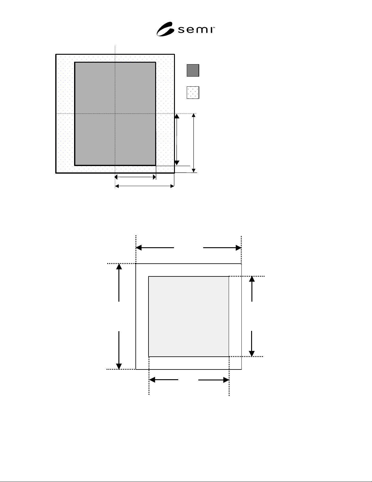
SEMI P40-1103 © SEMI 2003 3
Maximum printable
field
(4x) 104 by 132 mm
(26 by 33 mm at
wafer)
A
rea reserved for
alignment marks, ID
marks, and handling
(The position of these
items are to be
negotiated between user
and supplier.)
A
rea for patterns printed on wafe
r
66.0
76.0
76.0
52.0
CL
CL
Figure 1
Layout of the Front Surface of the EUVL Mask, Showing Areas Reserved for Printed Patterns, ID Marks,
Alignment Marks and Handling
Units are in millimeters, and CL identifies the dotted lines as centerlines.
L
D
W
Mounting
quality
area
L
Figure 2
Dimensions of Mounting Quality Area