semi合集-English.pdf - 第5997页
SEMI P43-0304 © SEMI 2004 6 surround(ing mask ar ea), pref erably clarified with a drawing, will replace the pitch inform ation. 7.23 measured fe ature inter-proximity error — measured value of feature inter-proximity er…
SEMI P43-0304 © SEMI 2004 5
7.17 measured mean X-Y deviation — the difference
between the mean values of measured feature widths in
X and Y directions, stating the same information as for
measured feature width uniformity (DEFAULT:
selecting the same values as used for measured feature
width uniformity.)
7.18 X-Y deviation uniformity — the spread of the
distribution of the difference between the width of all
considered feature widths in X and Y directions
(horizontal and vertical direction), stating the same
information as feature width uniformity. (DEFAULT:
selecting the same values as used for feature width
uniformity.)
NOTE 11: For such purpose X and Y feature width
measurement locations should be as close as practically
possible.
7.19 measured X-Y deviation uniformity — the spread
of the distribution of the difference between the width
of the measured feature widths in X and Y directions
(horizontal and vertical direction), including/stating the
same information as measured feature width uniformity.
(DEFAULT: selecting the same values as used for
measured feature width uniformity.)
7.20 feature linearity error — total range of the
deviations between the mask feature width and the
respective target width on a range of feature widths (see
Figure 6a), stating as mandatory information:
• the range of feature widths used (at mask level).
(DEFAULT is the interval from the critical
dimension to 5 times this value.)
NOTE 12: The ITRS uses a wider interval.
• all types and tones of features considered, e.g., line,
contact, space, etc. (see in Section 5 for definitions
of these terms). It is a strong recommendation to
fix on 1 tone and 1 type to reach a useful number.
DEFAULT is on lines (“line linearity error”).
Contacts may be more challenging (“contact
linearity error”).
• all orientations considered, e.g., horizontal and
vertical together, horizontal only, vertical only,
including other angles, horizontal-and-vertical
separately, etc.
• the pitch of the feature (or in general: a description
of the surround(ing mask area), see further), e.g.,
equal lines and spaces, isolated line, etc., or (if
wished, but not recommended) an interval of
pitches. DEFAULT is isolated features only,
which is defined as feature intra-proximity error.
NOTE 13: If a range of pitches is included, the resulting
definition will include (inter)proximity effects. (The
ITRS mask table assumes multiple pitches.)
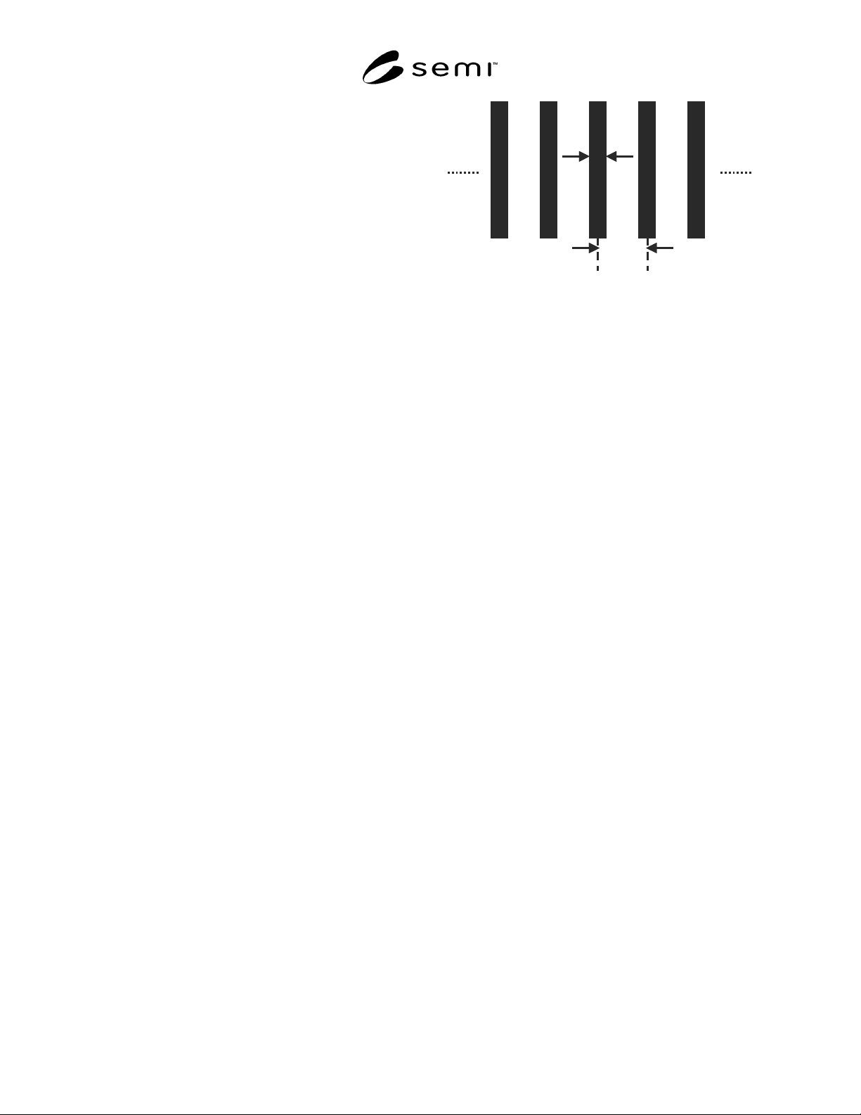
W
P
W
P
Figure 6
Choice of width (W) and pitch (P) in an array of
features (here shown for lines) for the determination
of a) feature linearity: varying W and P fixed;
b) feature interproximity: fixed W and varying P;
c) feature proximity: W and P BOTH varying.
7.21 measured feature linearity error — measured
value of feature linearity error, stating as mandatory
information in addition to that of measured feature
width and feature linearity error:
• the number of measurement points per feature
width (which is recommended to be more than one
measurement per feature width). If more than one
measurement per feature is taken, then the mean
value for each feature width is used.
and as optional information:
• the measured area.
• the spatial distribution of measurement locations.
7.22 feature inter-proximity error — range of the
deviations between the mask feature width of a given
size and the respective target width, on a variation of
local pattern density and configuration (i.e., of the
surround) (see Figure 6b), stating as mandatory info:
• the nominal feature width at mask level.
• all types and tones of features considered, e.g., line,
contact, space, etc. (see in Section 5 for definitions
of these terms). It is a strong recommendation to
fix on 1 tone/ 1 type to reach a useful number.
DEFAULT is on lines (line inter-proximity error).
• all orientations considered, e.g., horizontal and
vertical together, horizontal only, vertical only,
including other angles, horizontal-and-vertical
separately, etc.
• range of feature pitches. DEFAULT is equal lines-
and-spaces to isolated features. If only equal lines-
and-spaces and isolated features themselves (and
nothing in-between) are used, the term iso-dense
deviation can also be used. In more general cases
an alternative detailed description of the
SEMI P43-0304 © SEMI 2004 6
surround(ing mask area), preferably clarified with a
drawing, will replace the pitch information.
7.23 measured feature inter-proximity error —
measured value of feature inter-proximity error, stating
as mandatory information in addition to that of
measured feature width and feature inter-proximity
error:
• the number of measurement points used per pitch
or surrounding mask area (to be more than one
measurement per pitch). If more than one
measurement per pitch is taken, then the mean
value for each pitch is used.
and as optional information:
• the measured area on the mask.
• the spatial distribution of measurement locations.
7.24 feature proximity error — total range of the
deviations between the mask feature width and the
respective target width on a range of feature widths and
on a variation of local pattern density and configuration
(i.e., of the surround) (see Figure 6c), stating as
mandatory info:
• the range of feature widths used (at mask level).
(DEFAULT is the interval from the critical
dimension to 5 times this value.)
NOTE 14: The ITRS uses a wider interval.
• all types and tones of features considered, e.g., line,
contact, space, etc. (see in Section 5 for definitions
of these terms). It is a strong recommendation to
fix on 1 tone and 1 type to reach a useful number.
DEFAULT is on lines (“line proximity error”).
• all orientations considered, e.g., horizontal and
vertical together, horizontal only, vertical only,
including other angles, horizontal-and-vertical
separately, etc.
• range of feature pitches. In more general cases an
alternative detailed description of the surround(ing
mask area), preferably clarified with a drawing,
will replace the pitch information.
7.25 measured feature proximity error — measured
value of feature proximity error, stating as mandatory
information in addition to that of measured feature
width and feature proximity error:
• the number of measurement points used per pitch
or surrounding mask area (recommendation is > 1.
Then the mean value is used).
and as optional information:
• the measured area on the mask.
• the spatial distribution of measurement locations.
8 2D Mask Qualification Terminology
8.1 Introductory Remarks
8.1.1 The 2D terminology adds onto the 1D
terminology (Section 7). The 1D errors are an inherent
part of, and affect, the 2D qualification. Section 8.2
treats 2D-qualification without considering the impact
of 1D control (Section 7). Section 8.3 will suggest how
to include consequences of feature width deviation.
8.1.2 Most 2D definitions are based on a comparison of
a nominal and an actual feature/pattern. Where
relevant, appropriate alignment of nominal and actual
feature/pattern is assumed. This will be treated in detail
in Section
8.4.
8.2 True Values
NOTE 15: Reminder: The meaning of true is described in
Section 2.2. An ideal measurement then includes the idea of
perfect alignment of nominal and actual feature (see Section
8.4).
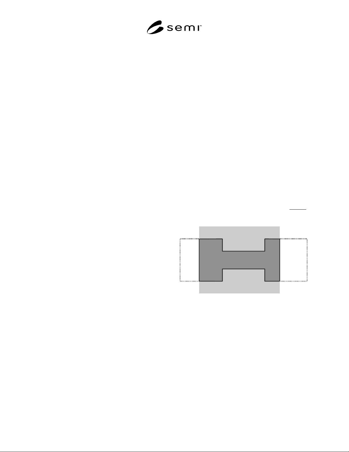
8.2.1 feature contour — shape formed by all edges of a
feature, including external and internal edges (see Note
3 in Section 5.10). If the feature considered is clipped
,
then the edge(s) clipped by the region of interest serve
as the edge(s) of the clipped feature (Figure 7).
ROI
Figure 7
Contour (for definition see Section 8.2.1, shown as a
full line,) of a clipped feature
(region of interest in light grey; the dotted line
shows the feature contour outside ROI)
8.2.2 General Approach, Based on Area
8.2.2.1 (clipped) feature area — enclosed area defined
by the edges of the (clipped) feature, i.e., area in the
(clipped) feature contour, mentioning as mandatory
information:
• description of the nominal feature including type,
dimensional information, tone, surrounding area,
and orientation relative to the coordinate system
(described in Section 6).
SEMI P43-0304 © SEMI 2004 7
• additionally if clipped: region of interest, clipping
details.
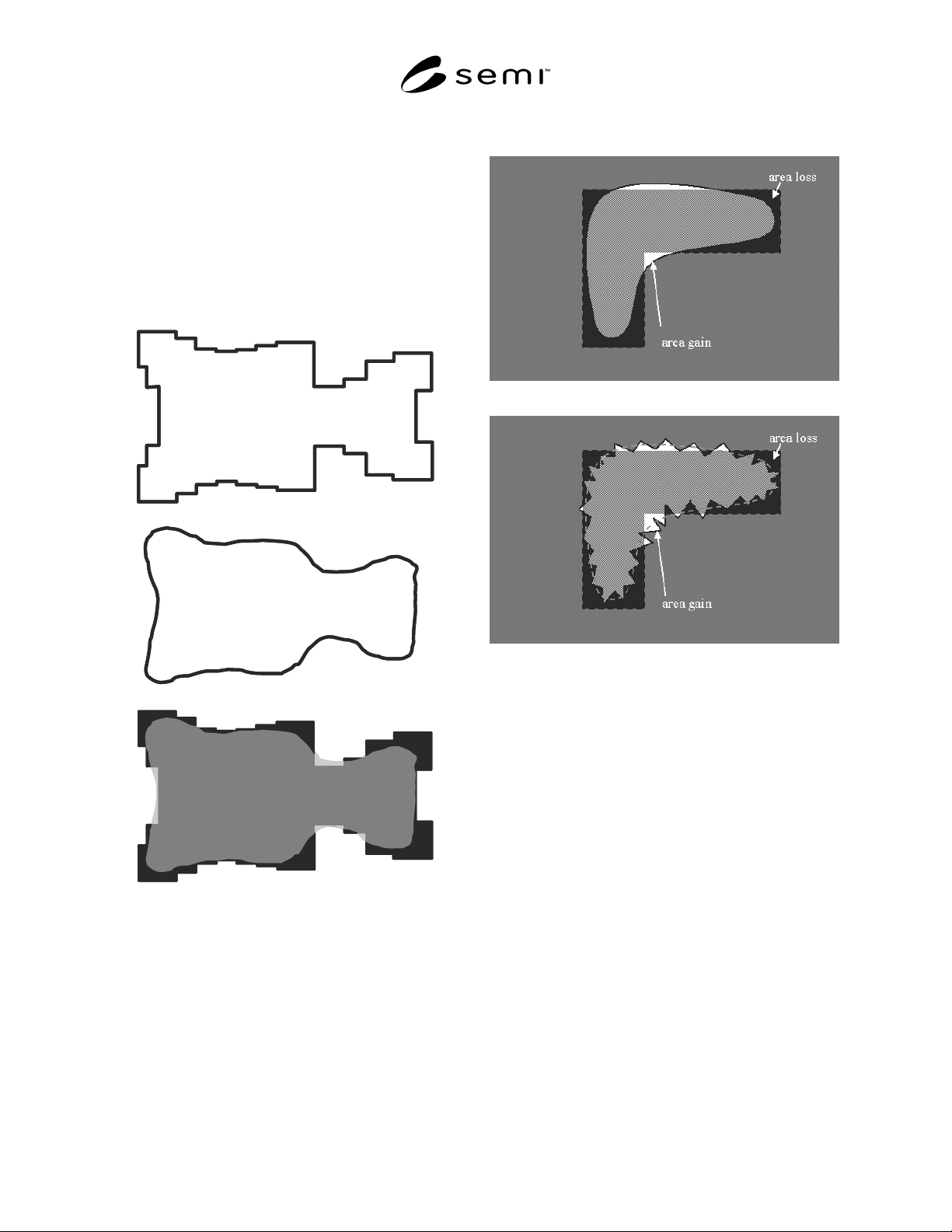
8.2.2.2 (clipped) feature area gain — area in the actual
(clipped) feature contour outside of the nominal
(clipped) feature (see Figure 8). Additional mandatory
information:
• relative position of actual and nominal feature (see
Section 8.4).
8.2.2.2.1 Note that the value of the (clipped) feature
area gain is always positive.
Figure 8
Illustration of feature area (top: nominal feature,
center: actual feature) and bottom: feature area
gain (light gray), feature area loss (black) and
overlapping area (medium gray)
8.2.2.3 (clipped) feature area loss — (clipped) area
outside of the actual feature, still inside of the nominal
feature (see Figure 8).
8.2.2.3.1 Same mandatory information as in (clipped)
feature area gain.
8.2.2.3.2 Note that the value of the (clipped) feature
area loss is always positive.
(a)
(b)
Figure 9
Illustration that edge roughness can influence
feature area deviation, unlike feature area
difference.
(a) without edge roughness (or with severe
smoothing)
(b) with edge roughness: area gain and area loss are
larger than in case (a), but can compensate each-
other when using feature area difference
8.2.2.4 (clipped) feature area difference — (clipped)
feature area gain minus (clipped) feature area loss. This
is also equal to the (clipped) feature area of the actual
feature minus the (clipped) feature area of the nominal
feature. The value of the (clipped) feature area
difference may be positive or negative accordingly.
Same mandatory information as in (clipped) feature
area gain.
NOTE 16: This qualification parameter is recommended for
contacts or dots, because in these cases it is of relatively
minor importance where the gain and loss are situated.
8.2.2.5 absolute (clipped) feature area deviation — the
sum of the values of (clipped) feature area gain and