semi合集-English.pdf - 第6001页
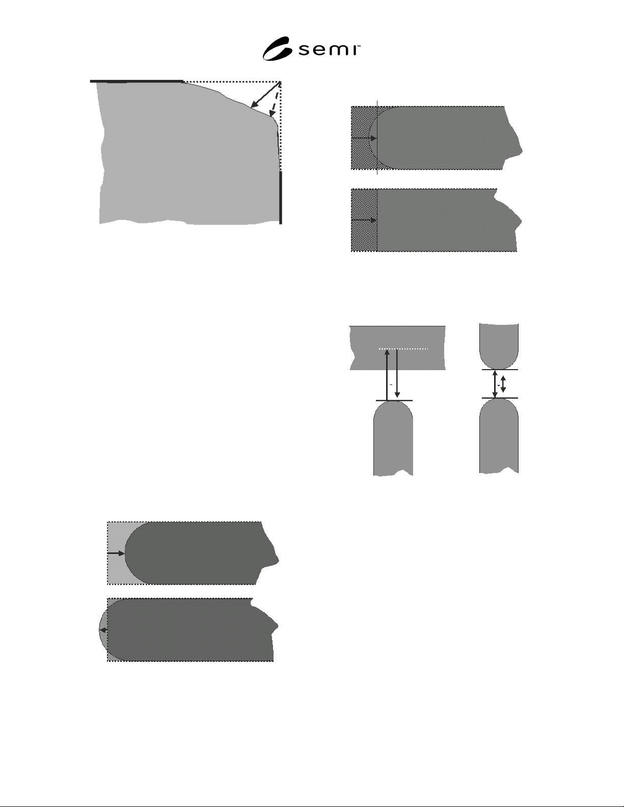
SEMI P43-0304 © SEMI 2004 10 Figure 14 Corner Pull-Back: Bisectric (Full Line Arr ow) vs. Minimum (Dotted Arrow) 8.2.4 Specific Case of Line-End Shortening 8.2.4.1 line-en d shortening — de viation of the actual feature …
SEMI P43-0304 © SEMI 2004 9
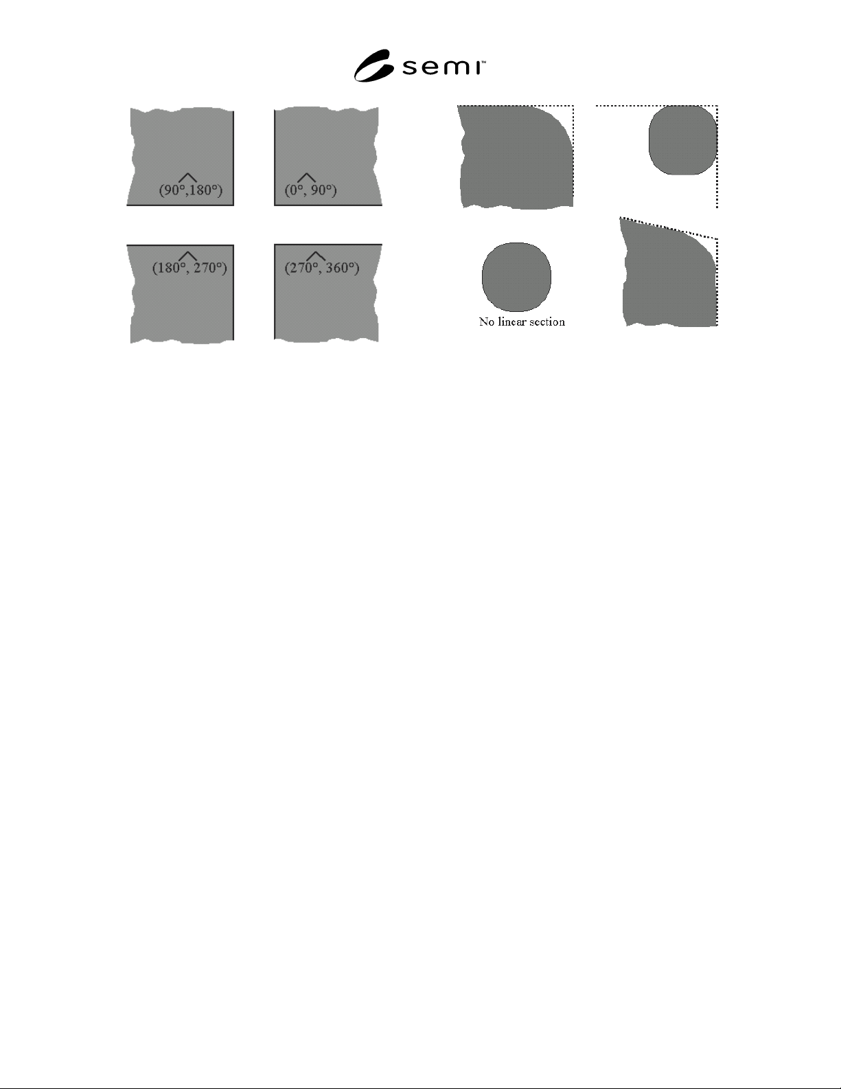
Figure 12
The 4 Default Orientations of a 90º Corner
8.2.3.2 corner area gain — special case of clipped
feature area gain, in which the region of interest
contains one corner of a feature.
8.2.3.3 corner area loss — special case of clipped
feature area loss, in which the region of interest
contains one corner of a feature.
NOTE 22: In non-corrected isolated cases normally there is
only a loss for outer corners and a gain for inner corners. In
other cases (i.e., corrected corners) there may be a loss and a
gain, which makes it necessary to also define the difference
and deviation, as done below.
8.2.3.4 corner area difference — corner area gain
minus corner area loss. As such it is a special case of
clipped feature area difference, in which the region of
interest contains one corner of a feature.
8.2.3.5 corner area deviation — the sum of corner
area gain and corner area loss. As such it is a special
case of clipped feature area deviation, in which the
region of interest contains one corner of a feature.
NOTE 23: As the corner shape is expected not to be decisive
for its printability (at least for an isolated corner), but rather
the balance between area gain and loss, it is recommended to
use area difference for corner qualification rather than area
deviation.
NOTE 24: Certain features with non-isolated corners, such as
line-ends and contacts, have specific definitions listed in
Sections 8.2.4 and beyond.
8.2.3.6 In present practice, corner rounding quantifica-
tion is done without comparison to the nominal corner.
However, this is only valid if the corner is isolated,
non-corrected, and its area gain is negligible. Typically
it is done based on the determination of a reference
corner which is obtained by the extrapolation of the
linear sections of the corner, if present (Figure 13).
Figure 13
Corner Rounding Determination by Extrapolation
of the Linear Sections of the Actual Feature Contour
8.2.3.7 equivalent corner rounding radius (ECRR) —
an equivalent, effective corner rounding radius
calculated from the area difference. It assumes that the
corner is a circular arc. The ECRR is calculated as
ECRR = sqrt( 4 * corner area difference / (π - 4) ), for a
90 degree corner.
8.2.3.7.1 The ECRR is defined only for negative corner
area differences, i.e., where the corner area loss is
larger than the corner area gain.
NOTE 25: This definition actually gives a 1D representation
for a 2D quality assessement, but it is found useful when
comparing mask quality to wafer printing results, which are
typically characterized by 1D measurements, such that a
dimensionless MEEF (mask error enhancement factor) can be
used. As with area based assessment, also this term
disregards the shape at the feature corner.
NOTE 26: Current methods to determine a corner rounding
radius based on fitting a circle to an actual corner have been
experimentally shown to deliver unreliable results and are
therefore strongly discouraged.
8.2.3.8 corner pull-back (CPB) — the distance
between the reference corner and the actual feature
contour
. This may be based on the minimum distance
(minimum CPB) or that determined along the bisectric
(bisectric CPB) (see Figure 14). The choice of CPB
technique is mandatory information.
NOTE 27: Edge roughness may have an important influence
on the corner pull-back, such that contour averaging may be
necessary to produce a meaningful result. The method of
contour averaging is mandatory information for corner pull-
back, if used.
SEMI P43-0304 © SEMI 2004 10
Figure 14
Corner Pull-Back: Bisectric (Full Line Arrow) vs.
Minimum (Dotted Arrow)
8.2.4 Specific Case of Line-End Shortening
8.2.4.1 line-end shortening — deviation of the actual
feature from the nominal feature at the nominal line-
end. This is still qualitative, and can be quantified in
general cases by overlaying the actual line contour to
the nominal line (see Section 8.4). Alternatively, a test
pattern such as Figure 17 may overcome the need to
overlay to the nominal case.
NOTE 28: “line-end” is also used for the darkfield case (for
spaces).
NOTE 29: In non-corrected isolated cases normally there is
only a loss (or shortening). In other cases (i.e., corrected line-
ends) there may be a loss and a gain (or extension), which
makes it necessary to also define the difference and deviation,
as done below.
NOTE 30: The minimum (= DEFAULT) region of interest
must include all feature area divergence until the feature can
be treated as one-dimensional (see Sections 5.3 and 5.4).
Figure 15
Quantification of line-end shortening by pull-back
(arrow) or area comparison. Top: shortening case,
below: extended case (e.g., caused by
overcompensation)
Figure 16
Quantification of line-end shortening by
equivalent line-end shortening (shaded area is equal
in the two figure halves)
Figure 17
Proposed test patterns to overcome the need to
overlay to the nominal case for the determination of
line-end shortening
8.2.4.2 line-end area gain — special case of clipped
feature area gain, in which the region of interest
contains a line-end.
8.2.4.3 line-end area loss — special case of clipped
feature area loss, in which the region of interest
contains a line-end.
8.2.4.4 line-end area difference — line-end area gain
minus line-end area loss. As such it becomes a special
case of clipped feature area difference, in which the
region of interest contains a line-end.
8.2.4.5 line-end area deviation — the sum of line-end
area gain and line-end area loss. As such it becomes a
special case of clipped feature area deviation, in which

SEMI P43-0304 © SEMI 2004 11
the region of interest contains a line-end. Mandatory
information for each of the 4 above:
• actual and nominal width,
• tone, pitch (or surrounding area), and
• orientation.
DEFAULT: isolated feature (line or space).
NOTE 31: As the line-end shape is expected not to be
decisive for its printability, but rather the balance between
area gain and loss, it is recommended to use area difference
for line-end qualification rather than area deviation.
8.2.4.6 line-end pull-back (LEPB) — the distance,
parallel to the line center, between the line-ends of the
nominal and the actual features (see Figure 15). This
distance may be determined along the line center
(center LEPB), or alternatively it may be determined by
the distance between the extreme point of the actual
line and the nominal line-end (minimum LEPB), in
analogy to corner pull-back. Mandatory information is:
• actual and nominal width,
• tone, pitch (or surrounding area),
• orientation, and
• choice of LEPB technique (center or minimum).
DEFAULT: isolated feature.
NOTE 32: Edge roughness may have an important influence
on the line-end pull-back, such that contour averaging may be
necessary to produce a meaningful result. The contour
averaging method is mandatory info for LEPB, if done.
8.2.4.7 equivalent line-end pull-back (ELEPB) —
defined as the negative line-end area difference divided
by the nominal line width (see Figure 16), assuming
accurate 1D control (see Section 8.1).
NOTE 33: This definition actually gives a 1D representation
for a 2D quality assessement, but it is found useful when
comparing mask quality to wafer printing results, which are
typically characterized by 1D measurements, such that a
dimensionless MEEF (mask error enhancement factor) can be
used. As with area based assessment, also this term
disregards the shape at the line-end.
NOTE 34: LEPB and ELES are positive when the actual line
is shorter than the nominal line. A negative sign is added in
case of over-correction, when the actual line becomes longer
than the nominal line.
8.2.5 Specific Case of Contacts and Dots
NOTE 35: This sub-section explains terminology for contacts
in full detail. This terminology can analogously be extended
to dots.
8.2.5.1 contact area — special case of feature area, in
which the feature is a contact (see Figure 18a).
8.2.5.2
contact area gain — special case of feature
area gain, in which the region of interest contains a
contact (see Figure 18b).
8.2.5.3 contact area loss — special case of feature
area loss, in which the region of interest contains a
contact (see Figure 18b).
8.2.5.4 contact area difference — contact area gain
minus contact area loss. As such it becomes a special
case of
feature area difference, in which region of
interest contains a contact.
8.2.5.5 contact area deviation — the sum of contact
area gain and contact area loss. As such it becomes a
special case of feature area deviation, in which the
region of interest contains a contact. Mandatory
information for each of the 4 above:
• nominal width in X and Y (Y not required for
square contacts),
• nominal area (not required for square or
rectangular contacts), and
• pitch (or the surroundings).
NOTE 36: The absolute value of the above qualification
parameters can be normalized to the nominal contact area,
i.e., normalized contact area deviation and normalized
contact area difference.
NOTE 37: As the contact shape is expected not to be decisive
for its printability, but rather the balance between area gain
and loss, it is recommended to use area difference for contact
qualification rather than area deviation.
8.2.5.6 contact X-width (or contact Y-width) — width
in X (or Y) of the smallest rectangle along X (or Y)
encompassing the contact (see Figure18c).
8.2.5.7 contact diagonal widths — widths determined
using the smallest rectangle encompassing the contact
confined along the directions
± arctan(W
Y,nominal
/W
X,nominal
) (see Figure 18d), which is
± 45degrees for square contacts.
NOTE 38: Edge roughness may have an important influence
on the 1D determination of contact width (X-, Y-, diagonal-),
such that contour averaging may be necessary to produce a
meaningful result. The contour averaging method used is
mandatory information for contact width and contact diagonal
width, as its influence is increasingly important for smaller
contacts (see Note 43 in Section 8.5).
8.2.6 Specific Case of Optical Proximity Correction
(OPC)
8.2.6.1 This document recommends to treat OPC’d
features or patterns as a special case of Section 8.2.1
(based on area). OPC fidelity is based on normalized
pattern area deviation and
normalized pattern area
difference.