semi合集-English.pdf - 第6102页
SEMI G20-96 © SEMI 198 0, 1996 2 5 Lead Finish 5.1 Tin Electroplate 5.1.1 Composition — T he tin shall n o t be less t han 99.8% pure ti n and s hall not contain more than 0.1% carbon. The depos it is Ty pe I as defined …

SEMI G20-96 © SEMI 1980, 19961
SEMI G20-96
SPECIFICATION FOR LEAD FINISHES FOR PLASTIC PACKAGES
(ACTIVE DEVICES ONLY)
1 Purpose
This specification defines lead finishes for plastic
packages (e.g., single-in-line, dual-in-line, quad-in-line)
utilizing leadframes with SEMI specified leadframe
materials.
2 Scope
This specification defines the composition, properties,
and limits and refers to the appropriate tests for utility.
3 Referenced Documents
Unless otherwise specified, the following standards and
specifications, with appropriate issue letter at time of
order entry, form a part of this specification to the
extent, and for the purpose, specified herein.
3.1 SEMI Specifications
SEMI G4 — Specification for Integrated Circuit
Leadframe Materials Used in the Production of
Stamped Leadframes
SEMI G18 — Specification for Integrated Circuit
Leadframe Material Used in the Production of Etched
Leadframes
SEMI G55 — Test Method Measurement of Silver
Plating Brightness
SEMI G56 — Test Method Measurement of Silver
Plating Thickness
3.2 ASTM Specifications
1
B 487 — Measuring Metal and Oxide Coating
Thickness by Microscopical Examination of Cross
Section
B 545 — Standard Specification for Electrodeposited
Coatings of Tin
B 567 — Measurement of Coating Thickness by the
Beta Backscatter Principle
B 568 — Measurement of Coating Thickness by X-Ray
Spectrometry
E 1B 571 — Adhesion of Metallic Coatings
E 10 — Standard Test Method for Brinell Hardness for
Metallic Materials
1 American Society for Testing Materials, 100 Barr Harbor Drive,
West Conshohoken, PA 19428-2959
E 384 — Standard Test Methods for Microhardness of
Materials
3.3 Federal Specifications
2
QQ-S-365 — Silver Plating, Electrodeposited, General
Requirements for
QQ-S-571 — Solder, Tin Alloy: Tin Lead Alloy, and
Lead Alloy
3.4 Military Specifications
2
MIL-G-45204 — Gold Plating, Electrodeposited
MIL-P-81728 — Plating, Tin Lead, Electrodeposited
MIL-STD-883 — Test Methods and Procedures for
Microelectronics
MIL-T-10727 — Tin Plating; Electrodeposits or Hot-
Dipped, for Ferrous and Non-Ferrous Metals
4 Application
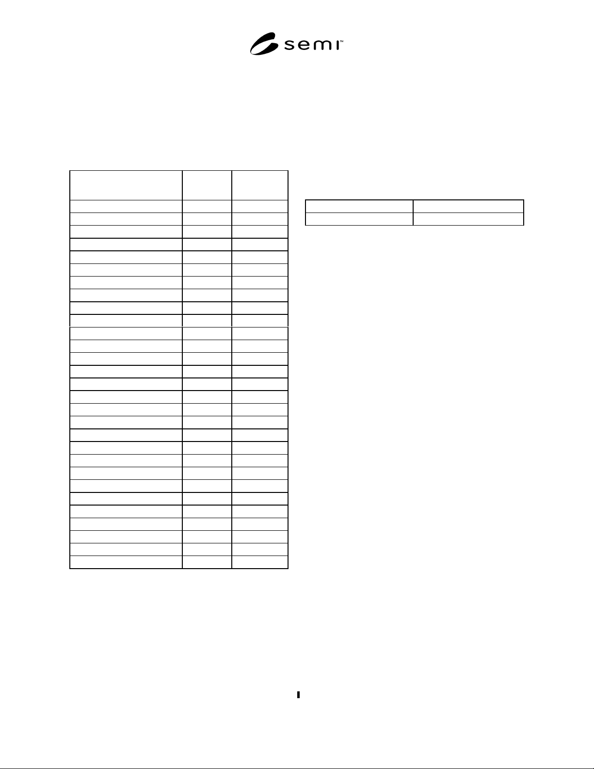
4.1 Table 1 lists recommended finishes for copper and
nickel/iron alloys.
4.1.1 Silver is approved as a lead finish for all alloys
but only for internal processing. When shipped to a
customer, silver must be removed and replaced by tin
lead.
4.1.2 Gold plate is usable in socketed applications as
well as in soldered applications. Hardness, grain size,
and other properties shall be specified on the
procurement drawing.
4.1.3 Solder, as used in this specification, refers to tin
lead as 63/37 or 60/40 unless otherwise specified and
agreed upon between user and supplier, and stated on
procurement drawings.
4.1.4 “Tinning” is a generic term (pr imarily used in
user industries) and means hot solder dip (near 60/40
tin lead) and not an application of tin.
4.2 Composition, limits, mechanical and physical
properties, and dimensions and tolerances for
leadframes are stated in SEMI G4 and SEMI G18.
4.3 Lead finish details are stated in Section 5.
2 Military Standards, Naval Publications and Forms Center, 5801
Tabor Ave., Philadelphia, PA 19120
SEMI G20-96 © SEMI 1980, 1996 2
5 Lead Finish
5.1 Tin Electroplate
5.1.1 Composition — The tin shall not be less than
99.8% pure tin and shall not contain more than 0.1%
carbon. The deposit is Type I as defined in MIL-T-
10727.
Table 1 Alloys
Finish Iron
Alloys
Finish Copper
Alloys
Tin MIL-T-10727
Tin (over base metal) X X
Acceptable Undercoats
1. Copper X X
2. Nickel X X
Tin Lead (Sn/Pb)
MIL-P-81728
Tin Lead (over base metal) X X
Sn/Pb
Acceptable Undercoats
1. Copper X X
2. Nickel X X
Solder Dip (Sn/Pb)
QQ-S-571
Solder Dip (over base metal) X X
Acceptable Undercoats
1. Copper X X
2. Nickel X X
3. Silver X X
Gold MIL-G-45204
Gold (over base metal) X
Acceptable Undercoats
1. Nickel X X
2. Copper Flash X
Silver QQ-S-365
Silver (over base metal) X X
Acceptable Undercoats
1. Copper X
2. Gold X
5.1.2 Characteristics — The procedure used for
evaluating the tin coating and the general requirements
for the coating shall comply with ASTM B 545 or the
latest current revision, except where noted below.
5.1.3 Thickness — The plated coating as measured on
the major flat of the leads shall be a minimum of 5
micrometers (200 microinches).
5.1.4 Appearance — The surface texture of the tin
shall be non-reflective matte finish.
5.1.5 Hardness — None specified.
5.1.6 Preservation — Preservation coating, if desired
and agreed upon by user and supplier, is acceptable.
(Example: Stearic acid solution in xylol as defined in
MIL-T-10727.)
5.2 Tin Lead (SnPb) Electroplate
5.2.1 Composition — Major constituents shall be tin
lead with minor impurities. Range of major constituents
shall be:
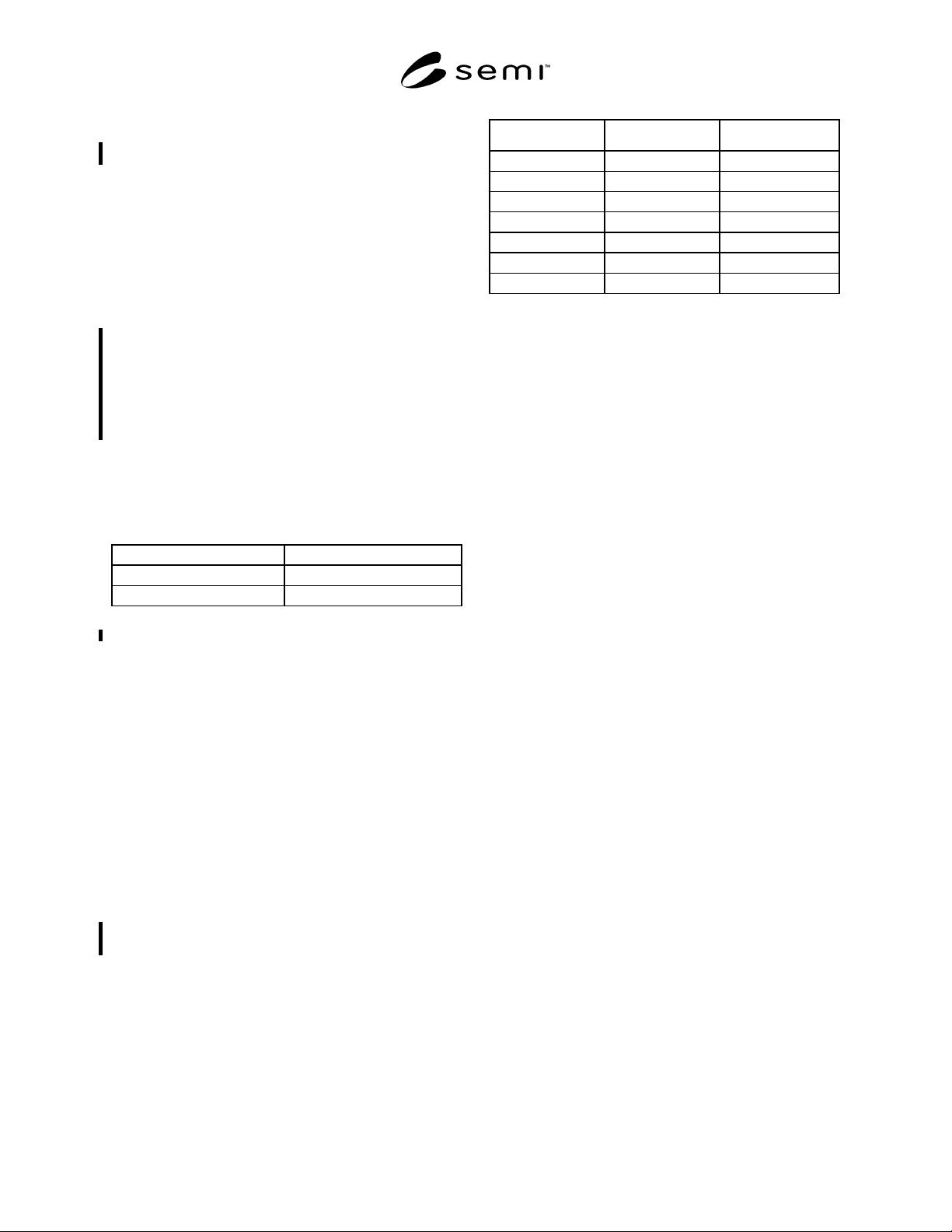
Tin 60%—95%
Lead 5%—40%
5.2.2 Purity and Application — Per MIL-P-81728.
5.2.3 Thickness — Shall be a minimum of 5
micrometers (200 microinches) measured on the major
flat of the leads.
5.2.4 The surface of the tin lead shall be non-reflective
matte finish.
5.2.5 Hardness — None specified.
5.3 Tin Lead Solder-Dip
5.3.1 Composition — 60/40 or 63/37.
5.3.2 Purity — As per Federal Specification QQ-S-
571.
5.3.3 Thickness — Shall be a minimum of 5
micrometers (200 microinches) as measured on the
major flat of the leads.
5.3.4 Process Conformance — Solder coating is
applicable as shown in Table 1. In addition, the coating
is acceptable as follows:
1. Over the electroplated tin or tin lead as per Section
5.1 or 5.2.
2. Over the electroplated silver as per Section 5.4.
3. Over the electroplated gold as per Section 5.5.
5.3.5 Appearance — Surface shall be smooth and
continuous.
5.3.6 Hardness — None specified.
5.4 Silver Electroplate
5.4.1 Composition — Silver electroplate shall be semi-
bright, Type II as per Federal Specification QQ-S-365,
Grade B, (without supplementary tarnish resistant
treatment).
5.4.2 Thickness — Shall be a minimum of 1.25
micrometers (50 microinches) as measured on the
major flat of the leads, in accordance with SEMI G56.
SEMI G20-96 © SEMI 1980, 19963
5.4.3 Appearance — Smooth and continuous and
semi-bright with minimum discoloration as measured,
in accordance with SEMI G55.
5.4.4 Hardness — Hardness shall be between 90 and
135 on the Brinell Hardness Scale, in accordance with
ASTM E 10.
5.4.5 Additional Processing
5.4.5.1 Due to chemical reactions, silver electroplated
surfaces should be protected from sulfur and sulfur
bearing materials such as note paper, cardboard, and
other like materials. Sulfur-free papers shall be used for
packing.
5.4.5.2 Prior to shipment to a user, devices with silver
electroplated leads shall have the silver removed and
replaced with tin lead coated leads, unless accepted by
contract.
5.5 Gold Electroplate
5.5.1 Composition — Gold plating shall be applied in
accordance with MIL-G-45204 in any and all of the
following grades depending on application.
Type I - 99.7 Percent minimum
Type II - 99.0 Percent minimum
Type III - 99.9 Percent minimum
NOTE 1: Type II is suitable for socketing application only.
5.5.2 Thickness — Shall be a minimum of 1.25
micrometers (50 microinches) as measured on the
major flat of the leads.
5.5.3 Appearance — Appearance of surface shall be
smooth and continuous. Attributes and defects are
specified in MIL-G-45204 (workmanship paragraph).
5.5.4 Purity — Composition limits are as specified in
Section 5.5.1 above. Individual metallics in the deposit
shall not exceed 0.1%. Metallic hardening agents,
purposely added to adjust a plating bath to specified
hardness, are not considered as impurities.
5.5.5 Hardness — Depending on Type and
Application, hardness is specified, using Knoop
indenter in the following categories (testing shall be in
accordance with ASTM E 384):
Type Grade Hardness (Knoop)
I A 90 max
B 91—129
C 130—200
II B 91—129
C 130—200
D 201 and over
III A 90 max
NOTICE: These standards do not purport to address
safety issues, if any, associated with their use. It is the
responsibility of the user of these standards to establish
appropriate safety and health practices and determine
the applicability of regulatory limitations prior to use.
SEMI makes no warranties or representations as to the
suitability of the standards set forth herein for any
particular application. The determination of the
suitability of the standard is solely the responsibility of
the user. Users are cautioned to refer to manufacturer’s
instructions, product labels, product data sheets, and
other relevant literature respecting any materials
mentioned herein. These standards are subject to
change without notice.
The user’s attention is called to the possibility that
compliance with this standard may require use of
copyrighted material or of an invention covered by
patent rights. By publication of this standard, SEMI
takes no position respecting the validity of any patent
rights or copyrights asserted in connection with any
item mentioned in this standard. Users of this standard
are expressly advised that determination of any such
patent rights or copyrights, and the risk of infringement
of such rights, are entirely their own responsibility.
Copyright by SEMI® (Semiconductor Equipment and Materials
International), 3081 Zanker Road, San Jose, CA 95134. Reproduction o
f
the contents in whole or in part is forbidden without express written
consent of SEMI.