semi合集-English.pdf - 第6148页
SEMI G31-0997 © SE MI 1986, 1997 2 7.3.4 Preheat pref ormed material to t h e req uired temperature. 7.3.5 Insert preheated m aterial into t r a ns fer pot and activate transfer ram (s emi-automatic mode). 7.3.6 Start st…
SEMI G31-0997 © SEMI 1986, 19971
SEMI G31-0997
TEST METHOD FOR DETERMINING THE ABRASIVE
CHARACTERISTICS OF MOLDING COMPOUNDS
1 Purpose
This document describes the method to measure the
abrasive characteristics of molding compounds by
measuring mold orifice weight loss as a function of
molded volume.
2 Scope
2.1 All thermoset molding compounds used for
microelectronic device encapsulation contain filler
materials, typically 60–90% — which contribute to
mold wear. Mold wear, typically at gates, is a major
reason for mold rework. This test method may be used
by suppliers to evaluate new molding materials or
control current materials or by customers to evaluate
the use of new materials. This test method provides a
comparison of abrasiveness between materials.
2.2 This procedure can be used to determine the
abrasive character of a given molding compound.
Knowing the conditions of test, the results of the test,
and the mold life experience (within one’s own
company) in the field, it is possible to judge if a
molding compound is more or less abrasive to current
compound in use.
3 Referenced Documents
3.1 Operational manuals for all equipment listed
within this document.
3.2 Mold compound data sheets
4 Method
This procedure determines the abrasive character of a
given filled molding compound by measuring orifice
weight loss as a function of extruded volume.
5 Interferences
5.1 Care must be taken to avoid orifice weight loss by
mishandling during placing and removing the orifice
from the mold base.
5.2 Before the orifice is re-weighed after molding,
carefully remove all contamination.
6 Equipment
6.1 Transfer molding press, 50 tons clamp minimum
6.2 Dielectric preheater
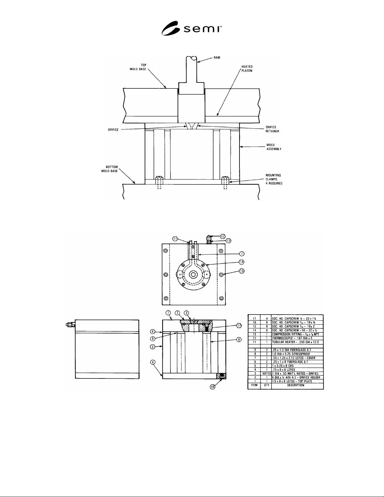
6.3 Orifice insert and mold assembly (See Figures 2–
6.)
6.4 Mold base with pot diameter 1.75 to 2.00 inches
6.5 Photoelectric safety light screen
6.6 Stop watch
6.7 Pyrometer
6.8 Force gauge
6.9 Asbestos gloves
7 Procedure
7.1 Equipment Set-Up — Orifice Mold Installation
(see Figure 1).
7.1.1 Place mold assembly on mold base and align
orifice retainer opening with center of transfer pot.
7.1.2 Clamp bottom plate of mold assembly to bottom
mold platen.
7.1.3 Set press limit switch to ensure clamp slow close
is initiated 1" from completion of mold closing.
7.2 Process Parameters
7.2.1 Set up the molding parameters according to the
material data sheet recommendations or expected use
conditions, if known. These conditions include:
• Mold temperature
• Pre-heat temperature or pre-heat time
• Transfer speed
• Transfer pressure
• Clamp pressure
• Cure time
NOTE: The charge weight to be determined by trial molding
shots to achieve a cull thickness between 0.060–0.120" and a
suitable weight of extrudate.
7.3 Operating Procedure
7.3.1 Weigh orifice to one ten-thousandth of a gram.
Record weight.
7.3.2 Verify process parameter settings.
7.3.3 Place orifice in orifice retainer and clamp mold
assembly.

SEMI G31-0997 © SEMI 1986, 1997 2
7.3.4 Preheat preformed material to the required
temperature.
7.3.5 Insert preheated material into transfer pot and
activate transfer ram (semi-automatic mode).
7.3.6 Start stopwatch when extrudate first appears.
Record total extrusion time.
7.3.7 Collect and weigh extrudate to nearest one tenth
of a gram. Record extrudate weight.
7.3.8 At the end of cure cycle, remo ve orifice from
retainer. Loosen set-screws to split orifice and, with
compressed air, blow out cured slug.
7.3.9 Ensure mating orifice halves are clean, realign
the halves and tighten set screws.
7.3.10 Place orifice in retainer and repeat steps 7.3.4
through 7.3.9.
7.3.11 Repeat steps 7.3.4 through 7.3.10 until a
minimum of 40 shots are run.
7.3.12 Record the following:
1. Original orifice weight
2. Shot number
3. Extruded weight per shot in grams
4. Cumulative extruded weight in grams
5. Orifice weight in grams
6. Orifice percent weight loss
7. Extrusion rate
8 Calculation
8.1 Orifice Weight Loss
I
O
− I
N
I
O
100%()= % wt. loss
I
O
= Initial orifice weight to ten thousandth of a gram
I
N
= Orifice weight after “N” number of shots to ten
thousandth of a gram
8.2 Plot on linear graph paper the orifice weight loss
vs. cumulative extruded weight.
8.3 Convert cumulative weight extruded to cumulative
volume extruded.
Example: Molding compound density 2.0 g/cm
3
cumulative weight = 2000 g
2000
2.0g
1000
3
3
g
cm
cm
×=
8.4 Convert cumulative volume extruded to equivalent
production mold shots.
Example: 28 mm × 28 mm × 3.4 mm - 208 Id PQFP
Package Volume:
28
1000
2 6656
3
mm × 28 mm × 3.4 mmx
cm
m
m
cm
3
3
=
.
Volume to shots:
1000 cm ×
sho
t
2.6656 cm
375 shots
3
3
=
8.5 Plot on linear graph paper the orifice weight loss
vs. equivalent production mold shots.
SEMI G31-0997 © SEMI 1986, 19973
Figure 1
Orifice Abrasion
Figure 2
Orifice Mold