semi合集-English.pdf - 第6180页
SEMI G38-0996 © SEMI 1987, 2004 5 7 Summary Report 7.1 The following d etails shall be specified: 1. Description of Package 1.1 Package Type Package Name ________________ (per JEDEC or EIAJ) Pin Counts ________________ p…

SEMI G38-0996 © SEMI 1987, 2004 4
measuring current, I
M
, used during the calibration
procedure). The DUT shall then be operated with
heating power (P
H
) applied. The temperature-sensitive
parameter, V
MH
, shall be measured with constant
measuring current, I
M
, that was applied during the
calibration procedure (see Step 1).
6.3.4.3.2 The heating power, P
H
, shall be chosen such
that the calculated junction-to-reference point
temperature difference as measured at V
MH
is greater
than or equal to 20°C. In accomplishing this, the device
under test should not be operated at such a high heating
power level that the on-chip temperature sensing and
heating circuitry is no longer electrically isolated. Care
should also be taken not to exceed the design ratings of
the package-interconnect system, as this may lead to an
overestimation of the power being dissipated in the
active area of the chip due to excessive power losses in
the package leads and wire bonds. The values of V
MH
,
V
MC
, and P
H
are recorded during the power application
test.
6.3.4.3.3 The following data shall be recorded for these
test conditions:
a. Temperature-sensitive electrical parameters (V
F
,
V
EB
, or other appropriate TSP).
b. Junction temperature, T
J
, is calculated from the
equation:
T
J
= T
R
+ V
MH
− V
MC
()
∆V
MC
∆T
MC
−
1
where T
R
= T
A
c. Ambient (air) temperature, T
A
.
d. Ambient (air) velocity, v
A
, (v
A
= 0 for still-air
enclosure).
e. Power dissipation, P
H
.
f. Mounting arrangement (including offset from test
board).
6.4 Calculations of R
θJR
6.4.1 Calculation of Package Thermal Resistance —
The thermal resistance of a microelectronic device can
be calculated when the junction temperature, T
J
, has
been measured in accordance with procedures outlined
in Sections 6.1 through 6.3. With the data recorded
from each test, the thermal resistance shall be
determined from:
R
θ
JR
=
T
J
−
T
R
P
H(Package)
where : R
θ
JR
=
R
θ
JA
and T
R
=
T
A
.

SEMI G38-0996 © SEMI 1987, 2004 5
7 Summary Report
7.1 The following details shall be specified:
1. Description of Package
1.1 Package Type
Package Name ________________ (per JEDEC or EIAJ)
Pin Counts ________________ pins
Special Specification ________________ Yes ________________ No
If Yes, describe the detail specification.
1.2 Test Chip
Chip per SEMI G32 ________________ Yes ________________ No
Chip Size ________________ mm x ________________ mm
Chip Thickness ________________ mm
1.3 Leadframe
Leadframe Material Fe/Ni Alloy, Cu, Cu Alloy, Other (____________ )
Leadframe Thickness ________________ mm
Die Pad Size ________________ mm x ________________ mm
1.4 Package Dimension & Compound
Package Size ________________ mm x ________________ mm
Package Thickness ________________ mm
Compound Material ___________________________________________
1.5 Others
Die Attach Material ____________________________________________
Heat Sink/Spreader ________________ Yes ________________ No
If yes, describe the configuration, dimension, method of attachment, location, etc.
2. Description of Test Board
Test Board per SEMI G42 ________________ Yes ________________ No
No. of Layers ___________________________________________
If test board is specified, describe the specification of the following items:
Dimension ________________ mm x ________________ mm x ________________mmt
No. of Layers ___________________________________________
Material ___________________________________________
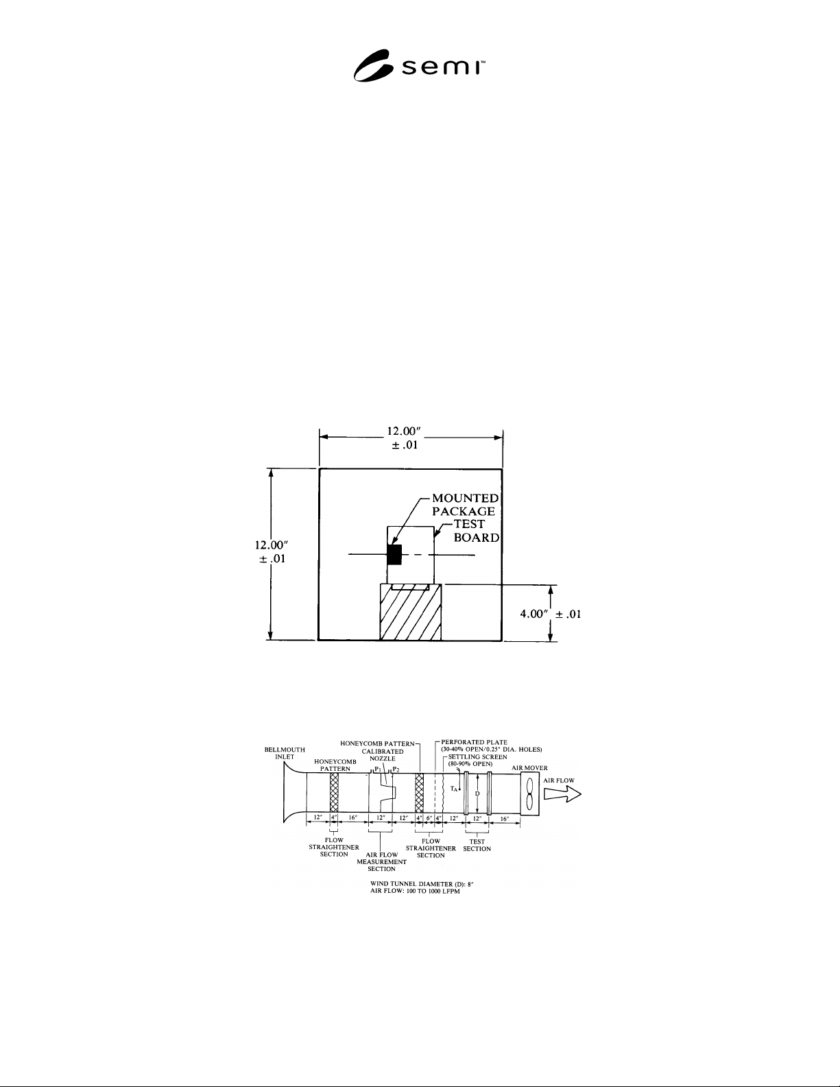
SEMI G38-0996 © SEMI 1987, 2004 6
Pattern ___________________________________________
3. Measurement Condition
Ambient Temperature, T
a
________________ °C
Ambient Humidity, H
a
________________ %RH
Air Velocity, V
a
0, 1, 2, 5, ( ) mm/sec.
Power Dissipation, P
H
0, 1, 2 W
4. No. of Samples, N
________________
5.
Thermal Resistance, R
θJA
________________ °C/W
8 Related Documents
8.1 Laboratory Methods of Testing Fans for Rating, AMCA Standard 210-74/ASHRAE Standard 51-75, Air
Movement and Control Association and the American Society of Heating, Refrigerating and Air-Conditioning
Engineers, 1975.
8.2 Fluid Meters — Their Theory and Application, American Society of Mechanical Engineers, Sixth Edition, 1971.
Figure 1
Test Board Positioning
Figure 2
Wind Tunnel Set-Up