semi合集-English.pdf - 第6192页
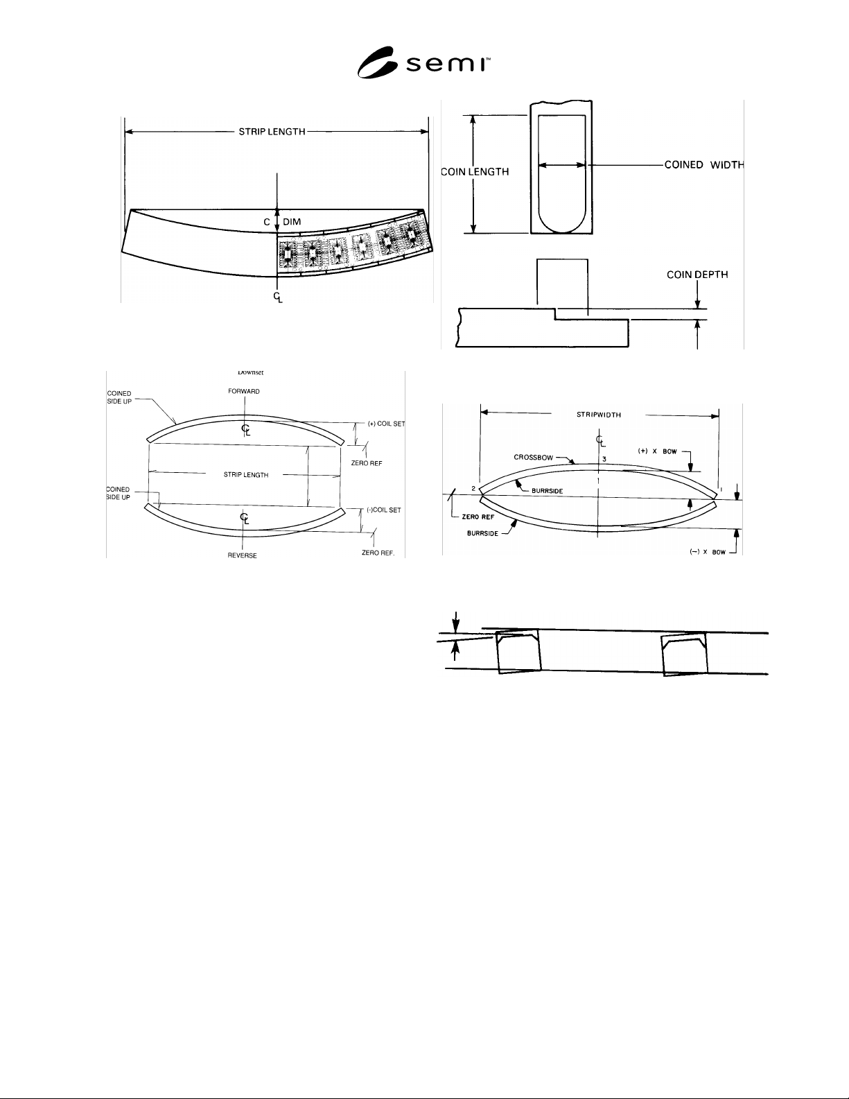
SEMI G41-87 © SEMI 1987 3 8.3 Figure 1 Camber Figure 2 Coil Set Figure 3 Coined Area Figure 4 Crossbow Figure 5

SEMI G41-87 © SEMI 1987 2
6.1.4 X-Y Plane Die Attach Pad Location — Die
attach pad to be located within ± 0.151 mm (0.002") as
measured from the centerline of the reference hold in
the side rail.
6.1.5 Lead Twist — Shall not exceed 330 or 0.015 mm
(0.0006") per 0.254 mm (0.010") of lead width.
6.1.6 Die Attach Pad Tilt and Flatness
6.1.6.1 Tilt — 0.025 mm (0.001") maximum per 2.54
mm (0.100") in the undepressed state. 0.051 mm
(0.002") maximum per 2.54 mm (0.100") in the
depressed condition.
6.1.6.2 Flatness — 0.0005 mm (0.0002") when
measuring from the center to the average of the four
corners. The corners are defined at 0.127 mm (0.005")
from each edge.
6.1.7 Die Attach Pad Downset — ± 0.051 mm
(0.002") as measured from the center of the pad to a
point on the bar support strip. The nominal downset
recommended is 0.30 mm (0.012") for 0.25 mm
(0.010") thick material and 0.20 mm (0.008") for 0.20
mm (0.008") thick material.
6.1.8 Lead and Die Attach Pad Coplanarity
6.1.8.1 Coplanarity — The relationship between the
leads and die attach pad is the axis relationship of these
parts to the Z plane.
6.1.8.2 Lead Planarity — The lead tips as measured in
the center of the back, uncoined surface of the lead tip
shall be located within the following tolerances of the Z
plane: Lead Planarity: ± 0.004".
6.1.8.3 Die Attach Pad Planarity — The die attach
pad when measured at the center must be within the
following tolerances of the Z plane: Pad Planarity: ±
0.003"/-0.005".
6.2 External Area and Strip
6.2.1 Material
6.2.1.1 0.20 mm (0.008") material thickness
recommended for 0.300" wide packages.
6.2.1.2 0.25 mm (0.010") material thickness
recommended for 0.300" wide packages.
6.2.1.3 Nominal thickness tolerances shall be ± 0.008
mm (0.0003").
6.2.1.4 Width Tolerance — ± 0.051 mm (0.002").
6.2.2 Coil Set — Maximum of 3.175 mm (0.125")
measured in a free standing state over strip length.
6.2.3 Crossbow — crossbow shall not exceed the
following dimensions: Maximum Crossbow ± 0.127
mm (0.005").
6.2.4 Camber — Shall not exceed 0.05 mm (0.002")
over a gauge length of 150 mm (6.00"). (See SEMI
G10, Section 8).
6.2.5 Progression — The progression over strip length
shall be within ± 0.051 mm (0.002") of nominal.
6.2.6 Burrs — Burrs shall be firmly attached and able
to withstand a probe force of 10 grams. Vertical burrs
inside the dambar shall not exceed 0.02 mm (0.001").
Vertical burrs outside the dambar and horizontal burrs
in any location shall not exceed 0.05 mm (0.002").
6.2.7 Pits and Slug Marks
6.2.7.1 Within functional area and on external leads
there shall be no slug marks. Pits shall not exceed .008
mm (0.0003") in depth and 0.013 mm (0.0005") in
largest surface dimension in these areas.
APPLICATION NOTE: There is a question regarding
the ability of material suppliers to meet this
specification. Revision of this specification is under
review.
6.2.7.2 Areas Other than 6.2.7.1 — Pits and
imperfections shall not affect leadframe strength
regardless of size and shall not exceed 0.05 mm
(0.002") in depth and 0.07 mm (0.005") in largest
surface dimension.
6.2.8 Strip Cutoff Location — Strip cutoff shall be
within ± 0.05 mm (0.002") of basic strip length.
7 Sampling
Sampling will be determined between user and supplier.
8 Packaging and Marking
8.1 Packaging — Leadframes must be packed in
containers designed and constructed to prevent damage
and/or contamination. Specific protection must be
provided against foreseeable mechanical and
environmental hazards.
8.2 Marking — The outer containers shall be clearly
marked, identifying the user stock number, user
purchase order number, drawing number, and vendor
lot number within the carton.
SEMI G41-87 © SEMI 19873
8.3
Figure 1
Camber
Figure 2
Coil Set
Figure 3
Coined Area
Figure 4
Crossbow
Figure 5
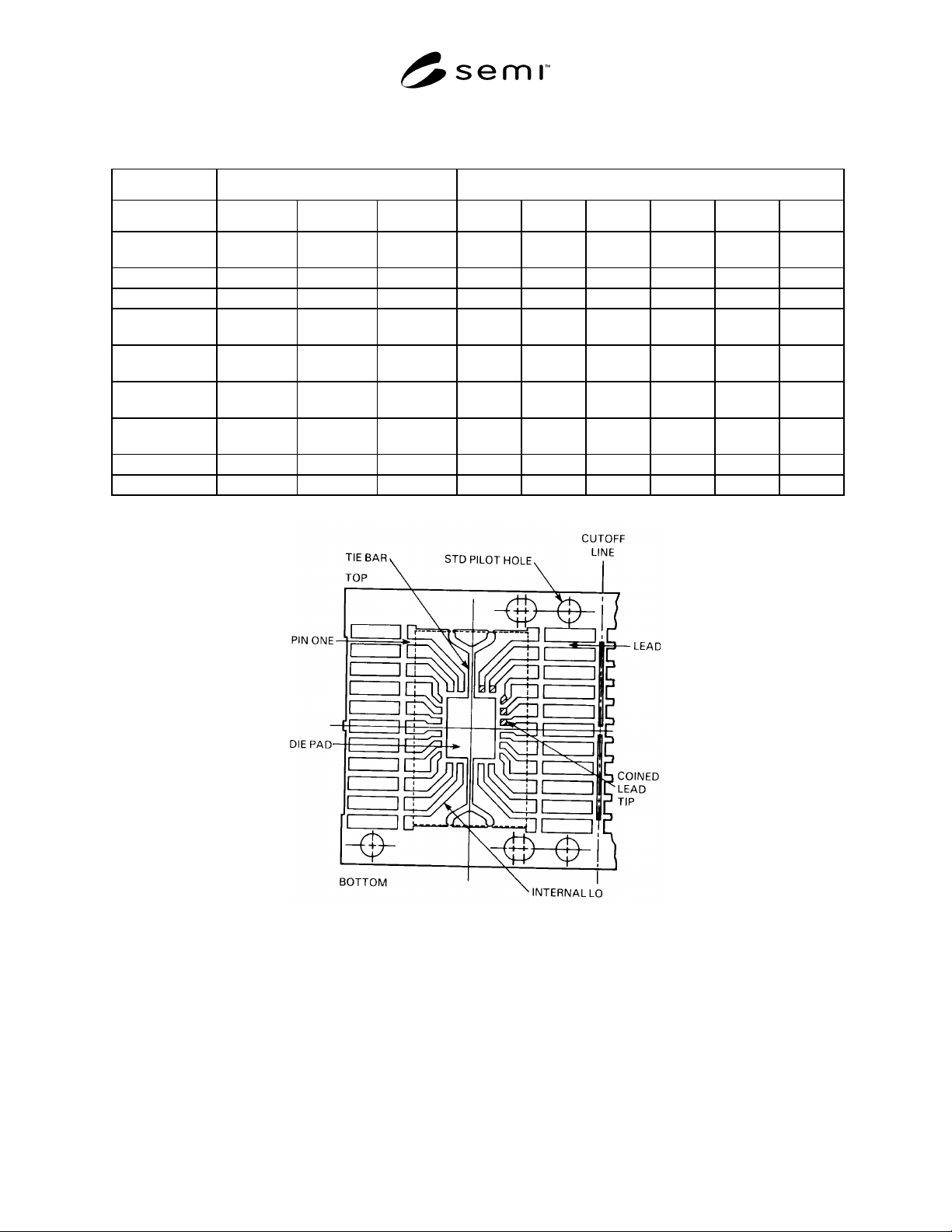
SEMI G41-87 © SEMI 1987 4
Lead Twist
Table 1 SOIC Dual Standard Dimensions
0.150 WIDE (NARROW) 0.300 WIDTH (WIDE)
8 14 16 141618202428
MATERIAL
GAGE
0.008 0.008 0.008 0.010 0.010 0.010 0.010 0.010 0.010
STRIP WIDTH 0.600 1.030 1.030 1.030 1.030 1.240 1.240 1.470 1.670
PROGRESSION 0.316 0.316 0.316 0.530 0.530 0.530 0.530 0.530 0.530
TOOLING
HOLE
0.060 0.060 0.060 0.060 0.060 0.060 0.060 0.060 0.060
DAMBAR
WIDTH
0.012 0.012 0.012 0.012 0.012 0.012 0.012 0.012 0.012
DAMBARDIST
ANCE
0.102 0.102 0.102 0.172 0.172 0.172 0.172 0.172 0.172
FROM PARTS
PER STRIP
20 24 24
STRIP LENGTH 6.32 7.584 7.584 7.42 7.42 7.42 7.42 7.42 7.42
PAD DOWNSET 0.008 0.008 0.008 0.012 0.012 0.012 0.012 0.012 0.012
Figure 6
Stamped Leadframe Terminology