semi合集-English.pdf - 第6213页
SEMI G43-87 © SEMI 198 6, 1987 1 SEMI G43-87 TEST METHOD FOR JUNCTION-TO-CASE THERM A L RESI STANCE MEA SUREMENTS OF MOLDED PLA STIC PACKAGES 1 Purpose The purpose of this test is to deter mine the thermal resistance of …
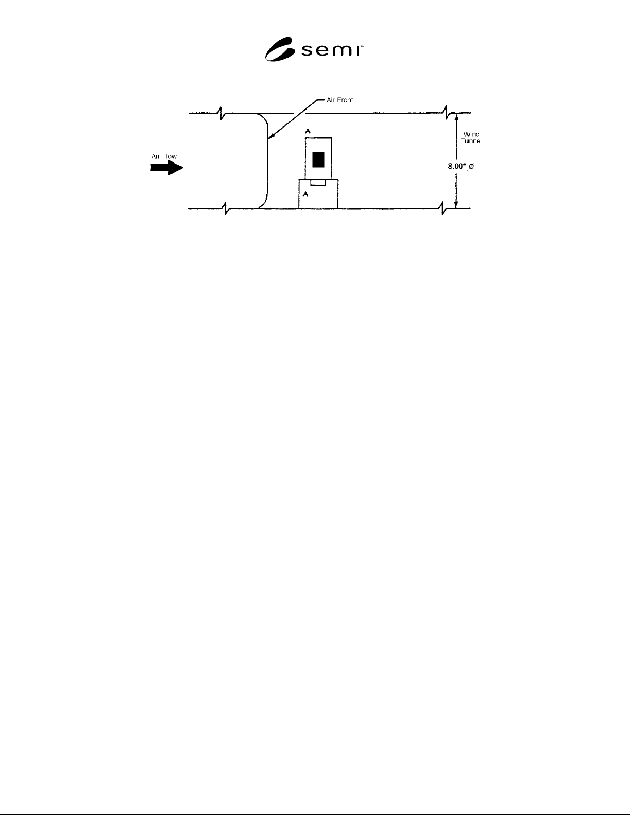
SEMI G42-0996 © SEMI 1986, 2004 15
Figure 14
Test Board Orientation Inside Wind Tunnel
NOTICE: SEMI makes no warranties or representations as to the suitability of the standards set forth herein for any
particular application. The determination of the suitability of the standard is solely the responsibility of the user.
Users are cautioned to refer to manufacturer’s instructions, product labels, product data sheets, and other relevant
literature respecting any materials mentioned herein. These standards are subject to change without notice.
The user’s attention is called to the possibility that compliance with this standard may require use of copyrighted
material or of an invention covered by patent rights. By publication of this standard, SEMI takes no position
respecting the validity of any patent rights or copyrights asserted in connection with any item mentioned in this
standard. Users of this standard are expressly advised that determination of any such patent rights or copyrights, and
the risk of infringement of such rights, are entirely their own responsibility.
Copyright by SEMI® (Semiconductor Equipment and Materials
International), 3081 Zanker Road, San Jose, CA 95134. Reproduction o
f
the contents in whole or in part is forbidden without express written
consent of SEMI.

SEMI G43-87 © SEMI 1986, 19871
SEMI G43-87
TEST METHOD FOR JUNCTION-TO-CASE THERMAL RESISTANCE
MEASUREMENTS OF MOLDED PLASTIC PACKAGES
1 Purpose
The purpose of this test is to determine the thermal
resistance of molded plastic packages using thermal test
chips. This test method deals only with junction-to-case
measurements of thermal resistance and limits itself to
fluid bath testing environments. For this test,
conduction through the leads is minimized, thus
providing information on the ability of the plastic
package material to dissipate heat. Due to the
thermophysical properties of the heat transfer fluids
used and the effects of the variable nature of the fluid-
stirring and package-mounting procedures, this test
method should only be used for comparing the thermal
characteristics of plastic packages in the same fluid bath
system.
2 Applicable Documents
2.1 SEMI Specification
SEMI G32 — Guideline for Unencapsulated Thermal
Test Chip
3 Definitions
The following definitions and symbols shall apply for
the purpose of this test:
case temperature, T
C
— in degrees Celsius. The case
temperature is the temperature at a specified accessible
reference point on the package in which the
microelectronic chip is mounted.
junction temperature, T
J
— in degrees Celsius. The
term is used to denote the temperature of the
semiconductor junction in the microcircuit in which the
major part of the heat is generated. For purposes of this
test, the measured junction temperature is only
indicative of the temperature in the immediate vicinity
of the element used to sense the temperature.
power dissipation, P
H
— in watts, is the heating power
applied to the device causing a junction-to-reference
point temperature difference.
thermal resistance, junction to specified reference
point, R
θJR
— in degrees Celsius/watt. The thermal
resistance of the microcircuit is the temperature
difference from the junction to some reference point on
the package divided by the power dissipation P
H
.
temperature-sensitive parameter, TSP — the
temperature-dependent electrical characteristic of the
junction under test which can be calibrated with respect
to temperature and subsequently used to detect the
junction temperature of interest.
4 Apparatus
The apparatus required for these tests shall include the
following as applicable to the specified test procedures:
a. Thermocouple material shall be copper-constantan
(type T) or equivalent, for the temperature range
-100 to + 300°C. The wire size shall be no larger
than AWG size 30. The junction of the
thermocouple shall be welded to form a bead rather
than soldered or twisted. The accuracy of the
thermocouple and associated measuring system
shall be ± 0.5°C.
b. Suitable electrical equipment as required to provide
controlled levels of conditioning power and to make
the specified measurements. The instrument used to
electrically measure the temperature-sensitive
parameter shall be capable of resolving a voltage
change of 0.5 mV.
c. Controlled temperature chamber or fluid bath
capable of maintaining the specified reference point
temperature to within ± 0.5°C of the preset
(measured) value. A typical temperature-controlled
fluid bath assembly is presented for illustrative
purposes only.
4.1 Fluid Bath Assembly — A typical temperature-
controlled fluid bath for thermally characterizing the
microelectronic device under test is shown in Figure 1.
In this figure, the package is mounted in a fluid bath
separate from the fluid circulator, although it can be
immersed directly in an integrated fluid circulator/bath
unit. The fluid in the bath should be continuously
stirred or agitated to ensure the required temperature
stability and uniformity. Since this working fluid is
being used as an infinite heat-sink, the case-to-fluid
(ambient) temperature difference at the case
temperature reference point of interest should be
minimized, i.e., ≤ 20°C. For case-to-fluid temperature
differences > 20°C, accuracy and repeatability
difficulties may occur due to a large variable
temperature gradient in the fluid film boundary layer at
the package-fluid interface. The case-to-fluid
temperature difference can be minimized by increasing

SEMI G43-87 © SEMI 1986, 1987 2
the fluid velocity and by decreasing the power density
seen by the fluid.
The device under test should be mounted such that heat
transfer to the fluid is not impeded. For leaded devices,
the leads should be oriented in such a manner so as not
to interfere with the heat transfer to the fluid and
provide freedom to any thermal currents caused by the
power dissipation within the package. The microcircuit
package shall be mounted such that conduction cooling
through the leads or test socket or both shall be small
compared to the other cooling mechanisms. To
minimize conduction through the leads, a special socket
jig that connects No. 36 AWG wire to the device socket
should be used.
The case temperature of the device under test should be
measured with a thermocouple that is attached to the
package/lead and should not be assumed to be at the
fluid temperature. The working fluid should have a
thermal conductivity at 25°C of at least 0.0006
W/cm°C. Working fluids such as inert fluorocarbon
liquids and silicone oils are suitable as cooling media.
5 Procedure
5.1 Direct Measurement of Reference Point
Temperature, T
R
= T
c
— For the purpose of measuring
a microelectronic device thermal resistance, the
reference point temperature shall be measured at the
package location of highest temperature which is
accessible from outside the package. This reference
point location is determined with the device operating
in free air and with no external heat-sinking. In general,
this reference point is found to be on the surface of the
body of the package, or on a lead near the body, in the
major path of heat flow from the chip heating surface to
the ambient fluid. The package surface may be altered
to facilitate this measurement provided that such
alteration does not affect the original heat transfer paths
and, hence, the thermal resistance, within the package
by more than a few percent.
5.1.1 Case Temperature, T
c
— The microelectronic
device under test shall be mounted under specified
conditions so that the case temperature can be held at
the specified value. A thermocouple shall be attached
on the surface of the device package directly under the
chip (i.e., on the base plane of the package). A
conducting epoxy may be used for this purpose. The
thermocouple bead should be in direct mechanical
contact with the package of the microelectronic device
under test. Care should be taken to minimize exposure
of the thermocouple bead to the high temperature
gradient in the fluid film boundary layer at the package-
fluid interface.
If it is found that attaching the thermocouple directly to
the case is impractical, an alternate approach using a
thermocouple welded to one side of a thin metal disk
should be used. This can be accomplished by parallel
gap welding the crossed thermocouple wires to one side
of a 0.25 cm (0.094 in) diameter, 0.02 cm (0.008 in)
thick beryllium-copper disk and then, with a thin layer
of adhesive, bonding the other side of the disk to the
case at the point of interest. The exposed thermocouple
bead/wire on the disk shall be covered with epoxy or
silicone rubber. The attached thermocouple should not
unduly interfere with heat transfer to the fluid.
5.2 Thermal Resistance, Junction-to-Specified
Reference Point, R
θJR
5.2.1 General Considerations — The thermal
resistance of a semiconductor device is a measure of the
ability of its carrier or package and mounting technique
to provide for heat removal from the semiconductor
junction. The thermal resistance of a microelectronic
device can be calculated when the case temperature and
power dissipation in the device and a measurement of
the junction temperature are known.
When making the indicated measurements, the package
shall be considered to have achieved thermal
equilibrium when halving the time between the
application of power and the taking of the reading
causes no error in the indicated results within the
required accuracy of measurement.
5.2.2 Indirect Measurement of Junction Temperature
for the Determination of R
θJR
— The purpose of the test
is to measure the thermal resistance of integrated
circuits by using particular semiconductor elements on
the chip to indicate the device junction temperature. In
order to obtain a realistic estimate of the operating
junction temperature, the whole chip in the package
should be powered in order to provide the proper
internal temperature distribution. During measurement
of the junction temperature, the chip heating power
(constant voltage source) shall remain constant while
the junction calibration current remains stable. It is
assumed that the calibration current will not be affected
by the circuit operation during the application of
heating power.
The temperature-sensitive device parameter is used as
an indicator of an average (weighted) junction
temperature of the semiconductor element for
calculations of thermal resistance. The measured
junction temperature is indicative of the temperature
only in the immediate vicinity of the element used to
sense the temperature.
The temperature-sensitive electrical parameters
generally used to indirectly measure the junction
temperature are the forward voltage of diodes and the