semi合集-English.pdf - 第6236页
SEMI G47-88 © SEMI 1988 3 mm) in depth and 0.0005" (0.00 13 mm ) in length (see SEMI G4). 6.6.2 They shall not affect lead stren g t h a nd shall not exceed 0.001" (0. 0254 mm) in depth and 0.002" (0.051 m…
SEMI G47-88 © SEMI 1988 2
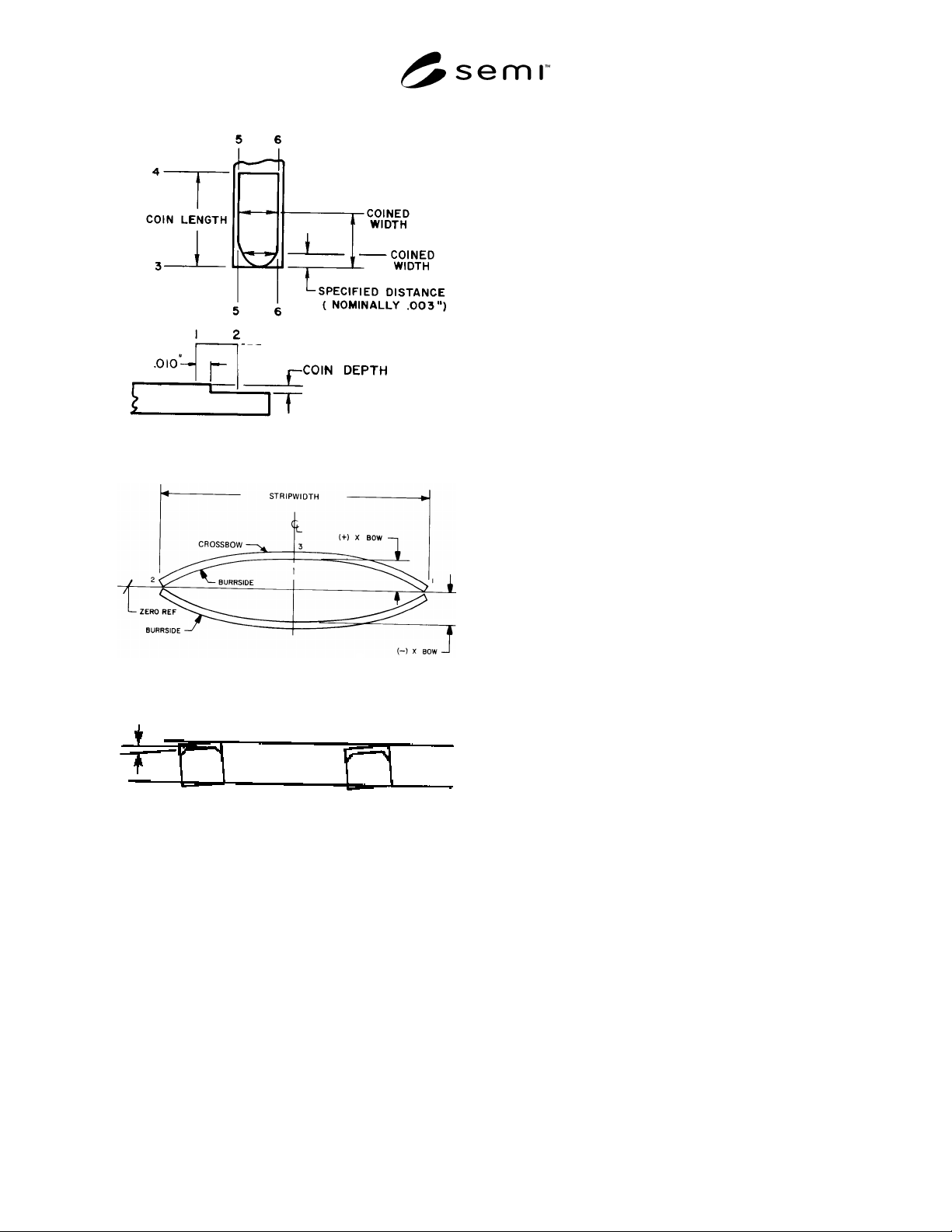
Figure 3
Coined Area
Figure 4
Crossbow
Figure 5
Lead Twist
4 Ordering Information
Purchasing orders for leadframes for plastic molded
quad flat pack packages furnished to this specification
shall include the following items:
4.1 Drawing no. and revision leve l.
4.2 Material, alloy specification.
4.3 Lead count, and confirming no . of units per strip.
4.4 Requirement for material certification.
4.5 Leadframe plating specifications.
5 Dimensions
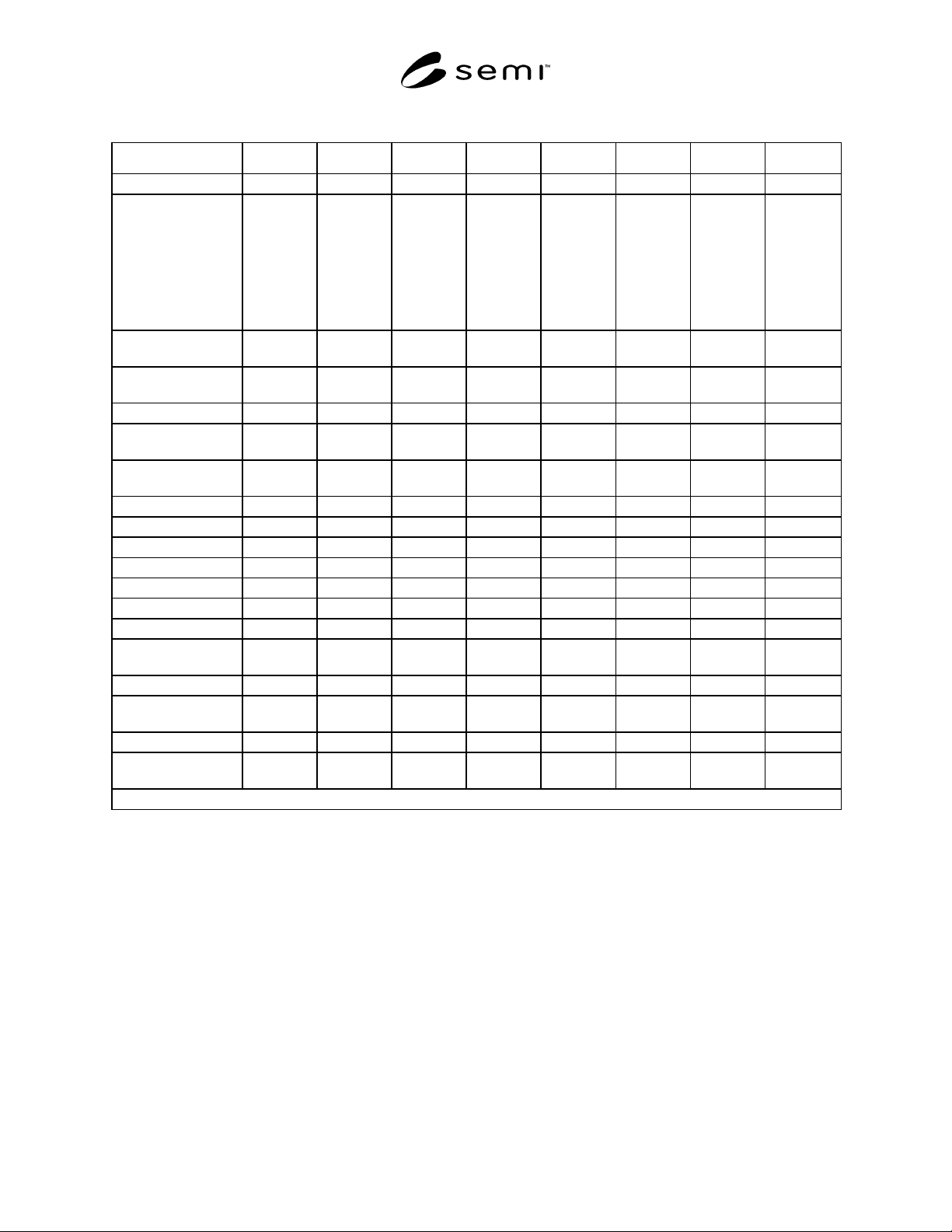
5.1 Tables 1, 2, 3, and 4.
5.2 Reference Figures 6 and 7 and Details A and B.
6 Defect Limits and Parameters (to measure,
see SEMI G10, Standard Method for
Mechanical Measurement for Plastic Package
Leadframes)
6.1 Lead Tip Width
6.1.1 Minimum Lead Tip Width — Shall be as agreed
to between supplier and purchaser.
6.1.2 Minimum Flat Wire Bonding Area — 80% of
nominal lead width and 0.025" (0.635 mm) in length.
6.2 Coining and Metal Clearance
6.2.1 Coined Depth — 0.0005" (0.013 mm) minimum
to 30% material thickness maximum (stamped frames
only).
6.2.2 Dimensions shown on drawings are before
coining.
6.2.3 Maximum Coining Bulge — (Stamped frame
only) shall not exceed 0.002" (0.051 mm) per edge and
shall be governed by metal to metal clearance
requirements (lead to lead and lead to pad).
6.2.4 Metal-to-Metal Clearance — Shall be as agreed
to between supplier and purchaser.
6.3 Lead Twist — Shall not exceed 3.5 or 0.0006"
(0.015 mm) per 0.001" (0.254 mm) of lead width.
6.4 Burrs — Shall be firmly attached and able to
withstand a probe force of 10 grams. All burrs vertical
and horizontal in any location shall not exceed 0.001"
(0.0254 mm).
6.5 Die Pad Tilt and Flatness — (See SEMI G10 for
measurement method.)
6.5.1 Tilt — 0.001" (0.025 mm) maximum per 0.100"
(2.54 mm) of length or width in the undepressed state,
and 0.002" (0.051 mm) maximum per 0.160" (4.06
mm) of length or width in the depressed state, when
measuring corner to corner: overall maximum not to
exceed a total of 0.006" (0.152 mm).
6.5.2 Flatness — 0.0002" (0.005 mm) per 0.100"
(2.54 mm) pad length when measuring from the center
to the average of four corners. The corners are defined
at 0.005" (0.127 mm) from each edge.
6.6 Pits and Slug Marks
6.6.1 Within the functional area and on external leads,
no slug marks and pits shall exceed 0.0003" (0.008
SEMI G47-88 © SEMI 19883
mm) in depth and 0.0005" (0.0013 mm) in length (see
SEMI G4).
6.6.2 They shall not affect lead strength and shall not
exceed 0.001" (0.0254 mm) in depth and 0.002" (0.051
mm) in length in non-functional areas.
6.7 Material thickness for both alloy 42 and copper
alloys is 0.006" (0.152 mm), ± 0.00015" (0.0038 mm)
for all lead counts.
NOTE — The material thickness tolerance dimension listed in
Section 6.7 is currently under committee review and is
expected to be revised to ± 0.0002".
6.8 Internal Position Tolerance — The centerline of
all leadframe features must be within T.P.T. 0.002"
(0.051 mm) relative to center line of pilot holes on rail.
6.9 Progression
6.9.1 Single progression of one frame is T.P.T. 0.002"
(0.051 mm).
6.9.2 Accumulated progression tolerance over the strip
length (measured from pitch line tooling hole to pitch
line tooling hole, across the strip length minus two
units) is within T.P.T. of 0.004" (0.102 mm).
6.10 Strip Cut Off Location — Shall be within T.P.T.
0.006" (0.154 mm) of nominal strip length.
6.11 Strip Width Tolerance — T.P.T. 0.004" (0.102
mm) for copper and alloy 42 materials.
6.12 Camber — Shall not exceed 0.002" (0.051 mm)
over nominal strip length.
6.13 Coil Set — Maximum of 0.020" (0.508 mm) over
the nominal strip length. This does not include material
thickness.
6.14 Cross Bow — Shall not exceed the following
dimensions:
No. of Leads Maximum Cross Bow
52—100 0.006" (1.52 mm)
132—164 0.010" (0.254 mm)
196—244 0.012" (0.305 mm)
7 Sampling
Sampling will be determined between supplier and
purchaser.
8 Packaging and Marking
8.1 Packaging — Leadframes must be packaged in
containers designed and constructed to prevent damage
and contamination.
8.2 Marking — The outer containers shall be clearly
marked identifying the user stock number, user
purchase order number, drawing number, and vendor
lot numbers within the carton.
SEMI G47-88 © SEMI 1988 4
Table 1 Leadframe Standard Dimensions
LEAD COUNT 52 LEAD 68 LEAD 84 LEAD 100 LEAD 132 LEAD 164 LEAD 196 LEAD 24 LEAD
PACKAGE SHAPE SQUARE SQUARE SQUARE SQUARE SQUARE SQUARE SQUARE SQUARE
JEDEC PACKAGE
DESIGNATION
PLASTIC
QUAD
FLAT
PACK
0.025"
SPACING
“GULL
WING”
PLASTIC
QUAD
FLAT
PACK
0.025"
SPACING
“GULL
WING”
PLASTIC
QUAD
FLAT
PACK
0.025"
SPACING
“GULL
WING”
PLASTIC
QUAD
FLAT
PACK
0.025"
SPACING
“GULL
WING”
PLASTIC
QUAD
FLAT
PACK
0.025"
SPACING
“GULL
WING”
PLASTIC
QUAD
FLAT
PACK
0.025"
SPACING
“GULL
WING”
PLASTIC
QUAD
FLAT
PACK
0.025"
SPACING
“GULL
WING”
PLASTIC
QUAD
FLAT
PACK
0.025"
SPACING
“GULL
WING”
NOMINAL
PACKAGE WIDTH
0.450 0.550 0.650 0.750 0.950 1.150 1.350 T.B.D.
NOMINAL
PACKAGE LENGTH
0.450 0.550 0.650 0.750 0.950 1.150 1.350 T.B.D.
STRIP LENGTH 8.800 8.640 8.640 8.400 8.400 8.000 7.200 T.B.D.
NO. OF UNITS PER
STRIP
10886654T.B.D.
TOOLING
DIMENSIONS
A 0.200 0.350 0.350 0.500 0.500 0.600 0.700 T.B.D.
(PROGRESSION) C 0.880 1.080 1.080 1.400 1.400 1.600 1.800 T.B.D.
F 0.050 0.050 0.050 0.050 0.050 0.050 0.050 T.B.D.
G 1.020 1.620 1.620 1.620 1.620 1.820 2.020 T.B.D.
(STRIP WIDTH) H 1.070 1.670 1.670 1.670 1.670 1.870 2.070 T.B.D.
I 0.810 0.910 1.010 1.110 1.310 1.510 1.710 T.B.D.
J 0.810 0.910 1.010 1.110 1.310 1.510 1.710 T.B.D.
DAMBAR
TOPACKAGE
0.030 0.030 0.030 0.030 0.030 0.030 0.030 T.B.D.
DAMBAR WIDTH 0.015 0.015 0.015 0.015 0.015 0.015 0.015 T.B.D.
EXPANSION SLOT
WIDTH
0.015 0.015 0.015 0.015 0.015 0.015 0.015 T.B.D.
DIAMETER Ø 0.060 0.060 0.060 0.060 0.060 0.060 0.060 T.B.D.
METAL
THICKNESS
0.006 0.006 0.006 0.006 0.006 0.006 0.006 T.B.D.
NOTE: ALL DIMENSIONS IN INCHES