semi合集-English.pdf - 第6248页
SEMI G48-89 © SEMI 1989, 1996 5 5.17.2 The measurement is made from the intersection of the straight part of the sh oulder with the shoulder bend radius of the lead on one side of the pac kage to the same point on the le…

SEMI G48-89 © SEMI 1989, 1996 4
mark (either ejector pin or Pin #1 indicator or other
feature).
5.13.3 The indicator is set to zero on the package
surface and then moved to the bottom of the feature.
The readout is read and recorded.
5.14 Dambar Trimming Defects — (Figure 4)
5.14.1 Equipment — Toolmaker’s Microscope
5.14.2 Measure from the edge of the lead to the edge of
the protrusion or intrusion; record the reading and the
lead number.
NOTE: Dambar trimming defects are those which can be
caused by overcutting into the lead shoulder (stand off) i.e.
cutting too much or undercutting the dambar, leaving too
much dambar or a burr. Overcutting causes shoulder
intrusions. Undercutting leaves shoulder protrusions. In some
cases, an adjacent protrusion and intrusion is caused by
misalignment of the part at the time of dambar removal.
5.15 Package Warpage — (Figure 5)
5.15.1 Equipment — Microscope “Z” Axis reading
40×.
5.15.2 With the package sitting on the stage, obtain a
two point datum by measuring two-points on opposite
edges 0.005 from the radius readings; move to the
center of the package and obtain the deviation from the
datum, and read and record the reading as the warp.
5.15.3 For quad packages, it is equally important that
there be minimum warp in each axis (X or Y) so that a
three-point Z axis datum must be obtained; the two
used in 5.15.2 and an additional one, on one adjacent
edge.
5.16 Lead Coplanarity
NOTE: Applies to all surface mount devices.
5.16.1 Contact Method — (Figure 6)
NOTE: Not recommended for gull-wing leads.
5.16.1.1 Equipment
Dial Indicator 0.0001" Accuracy, 5 grams maximum
pressure.
Granite Flat.
Transfer Stand.
Package Holding Fixture.
Reference Gauge Blocks, 0.0002" Accuracy.
5.16.1.2 Place the package on holding fixture so that
the flat sections of the leads, as they exit from the
plastic, are on the ground flats of the fixture. The leads
are to be facing “UP” (Dead Bug).
5.16.1.3 On the granite flat, set up the dial indicator on
its transfer stand and zero the reading using the
reference block. Use a suitable reference block so that
all measurements are positive to avoid confusion.
5.16.1.4 Measure the highest point on each lead (e.g.,
the tangent point of a “J” lead).
5.16.1.5 Determine the range of readings.
NOTE: Special Precautions
1. Be sure that the flat of the leadframe, as it exits
from the plastic, rests on the flats of the holding
fixture. If the radiused section supports the package,
then spurious readings will result.
2. The pressure exerted by the dial indicator must not
exceed 5 grams. To check the contact pressure of
the dial indicator, use a gram gauge. The gram
pressure must be noted at the initial deflection of the
gauge and at the maximum deflection of the gauge.
If the initial deflection is greater than 5 grams, then
the point where 5 grams is obtained must be noted
and the measurement must stay within this range to
be valid.
5.16.2 Comparator/Mirror Method
5.16.2.1 Equipment — Optical comparator with at least
20× magnification as per Section 3.1.2. Mirror, flat
within 0.0005 inch with a mirror finish having the
reflective suface on top. (A polished silver wafer is
suggested.)
5.16.2.2 Place the mirror on the measurement stage
mirrored side up with the mirror in the plane of the XY
axis. Place the package on the mirror with the leads
down. Sufficient mirror must extend past the leads
toward the lens of the comparator so that an image of
the leads with its reflection can be viewed. Focus on the
leads nearest the lens. (Care must be taken not to focus
on the leads on the opposite side of the package.) (See
Figure 8.)
5.16.2.3 Measure the distance between the lead tip and
its reflection. Divide that measurement by two to obtain
the coplanarity of the lead.
5.16.2.4 Repeat for each lead. Rotate part to measure
all sides. Determine co-planarity by identifying
maximum measurement.
5.17 Shoulder Bend Location — (Figures 1, 7, and 7a)
NOTE: This measurement is not precise, since radius tangent
locations allow for considerable inspector interpretation.
5.17.1 Equipment — Comparator at 20× magnifica-
tion. (Surface and shadow illumination).
SEMI G48-89 © SEMI 1989, 1996 5
5.17.2 The measurement is made from the intersection
of the straight part of the shoulder with the shoulder
bend radius of the lead on one side of the package to the
same point on the lead on the opposite side of the
package. Locate this point on the first lead by lining up
the vertical comparator cross hair with the straight of
the lead. Bring the center point of the cross hair to this
intersection. Zero the readout, move to the opposite
lead, and repeat the location of the intersection. Record
the measurement.
NOTE: Due to shadowing of leads, only the end leads on the
package can be measured. A visual check with a 10 to 20×
microscope should be made to check for gross difference of
other leads.
5.18 Surface Finish
5.18.1 Comparative Method — (EDM Finishes only)
5.18.1.1 Equipment — Charmille Standard Surface
Gauge Binocular Microscope and Light.
5.18.1.2 Insert gauge and molded package to be
checked into a holder so that both can be viewed at the
same time under the microscope.
5.18.1.3 Estimate the surface finish on the package.
5.18.2 Absolute Method
5.18.2.1 Equipment — Automatic Surface Analyzer
Surface Standards.
5.18.2.2 Calibrate the analyzer using the gauges.
5.18.2.3 Measure the surface finish on the package.
The analyzer gives the average roughness (R
a
) and the
actual surface roughness. Use average roughness for
acceptance.
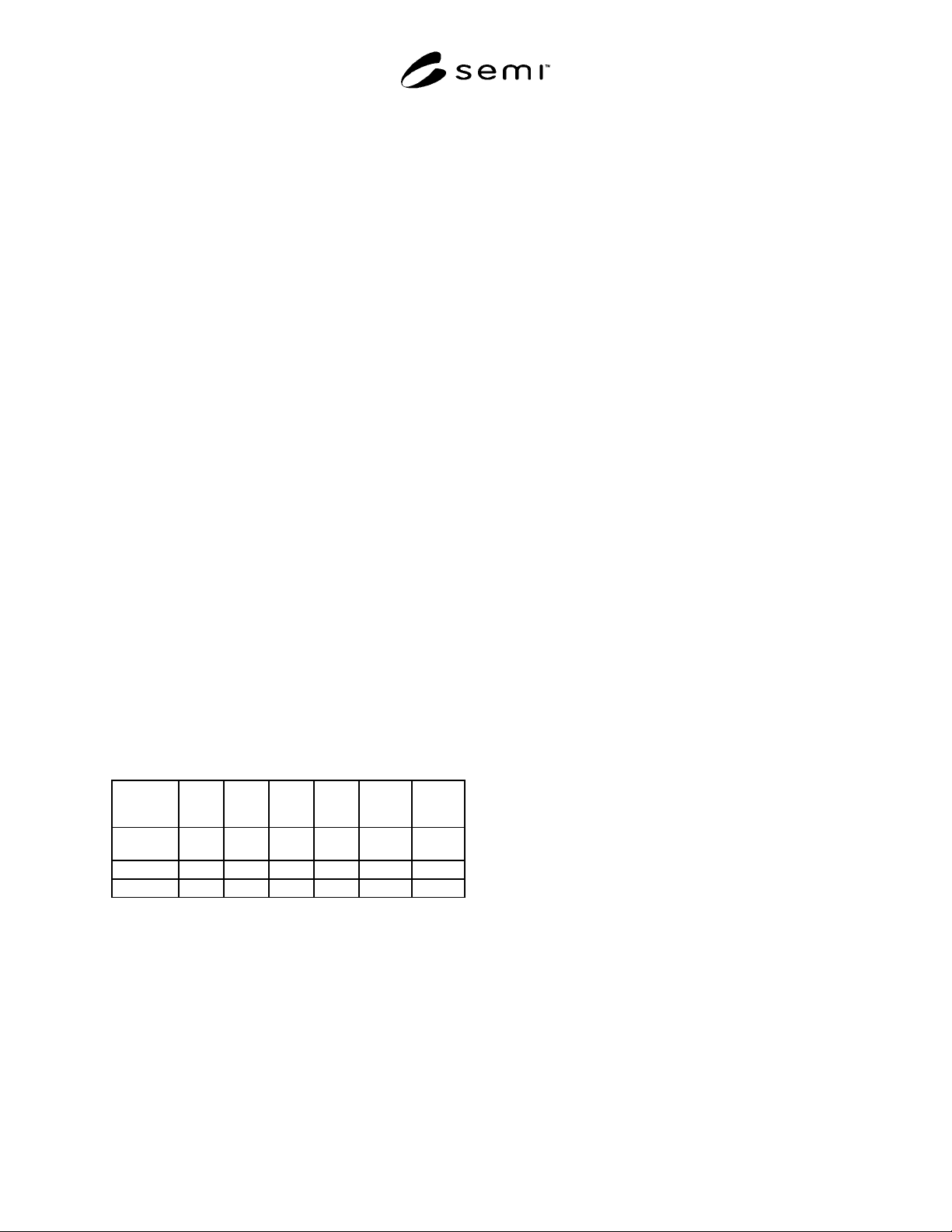
5.18.3 Table of approximate equivalent finishes
Mirror
Satin
Extra
Fine
Fine
Medium
Course
Micro
Inches
4 30 ± 10 50 ± 10 75 ± 10 105 ± 10 145 ± 10
Charmilles N/A N/A 18–21 21–24 24–27 27–30
Microns N/A 1 1.5 2 2.5 3.5
5.19 Radii
5.19.1 Comparative Method
5.19.1.1 Equipment — Optical comparator at 20×.
5.19.1.2 Radii are measured by comparison to known
radius overlays marked at the same magnification as the
comparator.
5.19.2 Absolute Method
5.19.2.1 Equipment — Toolmaker’s Microscope.
5.19.2.2 Radii are measured using the reticle lines and
the X and Y axes to obtain the radius.
5.19.2.3 Care must be taken to assure that each radius
is measured separately.
5.20 Lead Position
NOTE: Lead position is a combination of pitch variations due
to lead movement after forming and lead width. If the lead is
to fit a solder pad or hole, the combination must be
considered. In some cases, the lead width can be a major
contributor to poor lead position, eg. SO packages with gull-
wing leads, PCC with J bend.
5.20.1 Comparative Method
NOTE: This method will only determine if the part is usable,
not the breakdown of width and pitch variations.
5.20.1.1 Equipment — Optical Comparator at 20×.
5.20.1.2 Align the package to an overlay displaying
limit lines for lead pitch/width.
5.20.2 Absolute Method
5.20.2.1 Equipment — Toolmaker’s Microscope.
5.20.2.2 Move to the edge of the lead number and zero
the readout.
NOTE: Where there is a definitive end to the lead as in the
case of SO, SIP and DP, the end of the lead at the intersection
of the lead in feature, will be the measurement point. Quad
PCC packages will be measured at the top of the “J” bend
when in the “Dead Bug” position.
5.20.2.3 Move to the opposite edge of that lead and
record width.
5.20.2.4 Move to the first edge of the next lead. Record
the measurement. Repeat the width measurements.
5.20.2.5 Repeat for all leads to be measured.
5.20.2.6 Pitch can be calculated from the
measurements.
5.21 Draft Angles
5.21.1 Package Sides
5.21.1.1 Equipment — Optical comparator at 10x.
5.21.1.2 Lay the top or bottom surface of the package
squarely onto the comparator to insure that no
protrusions on the surface cause the package to be
tilted. Align the horizontal cross-hair to the leadframe.
Using the vertical cross hair, compare the draft angles
to an overlay.
NOTE: This measurement should be taken before the leads
are formed.
5.21.1.3 Repeat the procedure for all sides of the
package.

SEMI G48-89 © SEMI 1989, 1996 6
5.21.2 Pin Marks (e.g., Pin 1 indicator at end of
package).
5.21.2.1 Equipment — Toolmaker’s Microscope.
5.21.2.2 Focus the microscope on the surface of the
package and measure the diameter of the pin hole. (D1)
5.21.2.3 Focus on the bottom surface of the pin hole
and measure the diameter. (D2)
5.21.2.4 Tangent of Draft angle = (D1 – D2)/2H where
H is pin depth from Section 5.12 or cavity thickness.
5.21.2.5 In some cases ejector pin holes may require
measurement if a deep hole is specified.
5.22 Lead Spread — (Figures 1, 7, and 7a)
5.22.1 MDIP, SO — (Figure 7, 7a)
5.22.1.1 Equipment — Optical Comparator at 10×
Magnification.
5.22.1.2 Place the package squarely on the comparator
with the leads “UP” and find the mid-point of the
bottom cavity width.
5.22.1.3 Measure the distance to the outer edge of each
row of leads at the widest point of spread.
5.22.2 PCC (J bend lead dimension) (Foot Print)
Measure from perpendicular to the greatest extension of
the “J” radius of the leads on one side of the package to
the perpendicular tangent to the greatest extension of
the “J” radius of the leads on the opposite package side.
(See Figure 1.)
5.23 Foot Angle — (Figure 7)
NOTE: Applies to gull-wing leads.
5.23.1 Equipment — Optical Comparator at 20×
Magnification. Device Holding Fixture (see Section
5.16).
5.23.2 Place the device in the fixture, so that the flat
section of the leadframe at the junction with the plastic
body rests on the fixture’s flats. Leads to be facing
“UP”.
NOTE: Do not rest the radiused sections of the leads on the
flats. Be sure that all mold flash is removed from the area of
the frame that rests on the flats.
5.23.3 Measure the angle of the foot with respect to the
horizontal.
5.24 Foot Length — (Figure 7)
NOTE: Applies to gull-wing leads.
5.24.1 Equipment — Optical Comparator at 20×
Magnification. Device Holding Fixture (see Section
5.23).
5.24.2 While the foot angle is being measured, place a
circle template that contains the same radius as the
formed part onto the comparator. Align this template to
the radius of the outside bend. Where the radius of the
template meets the radius of the outside bend, this is the
tangent point to measure foot length.
5.25 Stand-Off
5.25.1 Measure the plastic stand-off, when applicable,
using the procedures of Section 5.12.
5.26 Lead Sweep
5.26.1 Equipment — Toolmaker’s Microscope or
Optical Comparator.
5.26.2 Method
5.26.2.1 Determine centerline of lead at egress of lead
from molded body (CL1) (see Figure 4).
5.26.2.2 Determine centerline at the end of the lead
(CL2). The difference between the two centerlines
CL2 – CL1, shall be the lead sweep.
NOTE: On “J” lead devices, the end of the lead is defined as
the bottom of the “J” lead radius.
5.26.3 Cautionary Notes
5.26.3.1 Verify centerlines on leadframe before
measuring to ensure lead-frame is correct.
5.26.3.2 Verify lead position in relation to the top
cavity centerline.