semi合集-English.pdf - 第6310页
SEMI G61-94 © SEMI 1994 10 8.1.5.4 Sol der Pad Adhesion — Per T e s t Condition D if specified by ag ree ment between vendor and customer. 8.1.6 St ud Integrity — Shall be eval u a te d per MIL- STD-883, Method 2004, T e…
SEMI G61-94 © SEMI 19949
Any pin, lead, heat sink/stud braze areas where more
than 5% of the periphery is not covered by the braze
fillet and any voids extend under the brazed element.
7.3.11 Mechanical Damage
7.3.11.1 Broken, Kinked, or Missing Pins or Leads
7.3.11.2 Twist — Any pin or lead twist ed by more
than 10° from the untwisted condition.
7.3.11.3 Pin or Lead Sweep — Any location of the tip
of the pin or lead exceeding 0.010" (0.0254 mm) away
from the vertical (or horizontal, for flat packs) datum
passing through the mid-point of the pin or lead at the
point of brazing to the contact pad.
7.3.11.4 Pin or Lead Tweeze — Any location of the
tip of the pin or lead exceeding 0.010" (0.0254 mm)
away from the vertical datum passing through the mid-
point of the pin or lead at the point of brazing to the
contact pad.
7.3.11.5 Threads — Any damage to the threads on
studs.
7.4 Package Construction
7.4.1 Pins and Leads — Location.
7.4.1.1 Pin or Lead Offset — Any offset from the pin
or lead true position exceeding 0.005" (0.127 mm).
7.4.1.2 Lead-to-Lead or Pin-to-Pin Separation — Any
separation exceeding 10% of the designed separation,
up to an allowable maximum of 0.010" (0.254 mm).
7.4.1.3 Side-to-Side Misalignment — Any
misalignment exceeding the limits shown in Table 6.
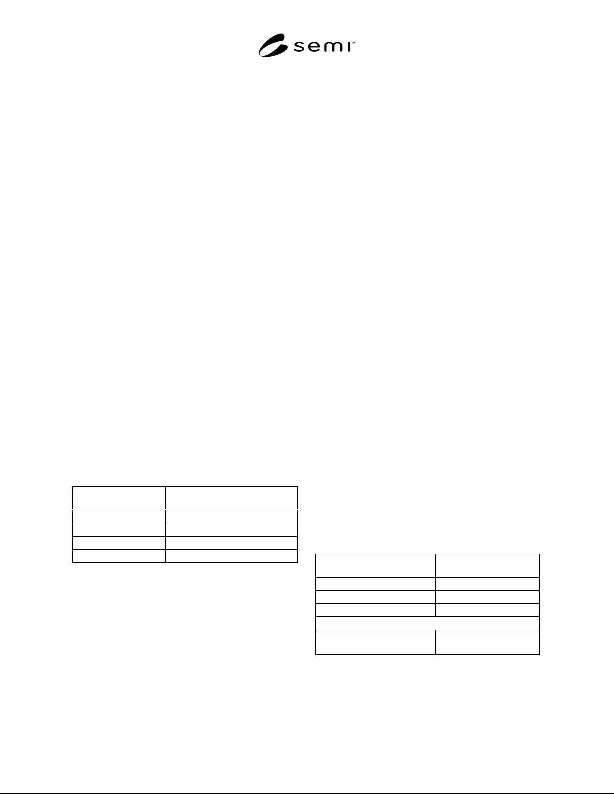
Table 6
Package Type
Maximum Allowable Side-to-Side
Misalignment inch (mm)
Dual-in-Line 0.010 (0.254)
Flat Packs 0.005 (0.127)
Leaded Chip Carriers 0.005 (0.127)
Pin Grid Arrays 0.005 (0.127)
NOTE 19: During inspection, the combination of offset,
separation, and side-to-side misalignment shall also meet
limits agreed between user and supplier.
7.4.2 Ceramic Layer Misalignment — Any
misalignment between layers exceeding 0.005" (0.127
mm) in either the X or Y planes.
7.4.3 Metallization Alignment to Ceramic — Any
misalignment exceeding the limits defined on the
package drawing.
8 Incoming Inspection and Functional Tests
8.1 Incoming Inspection — Packa ges shall be
inspected in the following sequence.
8.1.1 Dimensional inspection to the requirements of
Section 5. All dimensions shall be measured by
techniques agreed between supplier and customer
except as follows:
8.1.1.1 Seal ring flatness shall be measured per SEMI
G6.
8.1.2 Visual inspection per Section 7.
8.1.3 Metallization — Plating.
8.1.3.1 Thickness — Shall be measured by x-ray
fluorescence per ASTM B 568. The location of the
areas to be measured, which include die and wire bond
and seal ring areas, the tolerance and acceptable
standards shall be agreed between user and supplier.
8.1.3.2 Temperature Resistance — Sh all be evaluated
per SEMI G8.
8.1.3.3 Plating Hardness — Die and wire bond and
seal ring areas — shall be measured per ASTM B 578
to limits defined by MIL-G-45204 if specified by
agreement between vendor and customer.
8.1.3.4 Pin, Lead, Solder Castellation, or Solder Pad
Solderability — Shall be tested per SEMI G35.
8.1.4 Pin, Lead, Seal Ring, or Heat Sink/Stud
Hardness — Shall be measured per ASTM E 18 if
specified by agreement between vendor and customer.
8.1.5 Pin or Lead Integrity — Shall be evaluated per
MIL-STD-883, Method 2004.
NOTE 20: After each test, the plating shall be evaluated for
continuity per SEMI G35.
8.1.5.1 Tension — Per Test Condition A except as
shown in Table 7.
Table 7
Pin/Lead Dimension
inches (mm)
Minimum Tension
lbs (kg)
Round Pin
0.008 (0.203) 1.0 (0.455)
0.018 (0.457) 10.0 (4.55)
Rectangular Lead
0.018 ×=0.010
(0.457=×=0.254)
10.0 (4.55)
8.1.5.2 Fatigue — Per Test Condition B2 if specified
by agreement between user and supplier.
8.1.5.3 Torque — Per Test Condition C1 if specified
by agreement between user and supplier.

SEMI G61-94 © SEMI 1994 10
8.1.5.4 Solder Pad Adhesion — Per Test Condition D
if specified by agreement between vendor and
customer.
8.1.6 Stud Integrity — Shall be evaluated per MIL-
STD-883, Method 2004, Test Condition C2. Torque to
be agreed between user and supplier.
8.1.7 Heat Sink Integrity — Test sha ll be agreed
between user and supplier.
8.2 Functional Testing — The seq uence of functional
testing shall be as shown in Figure 9. (Packages shall be
sequentially subjected to all tests.)
NOTE 21: All procedures used to functionally test the
components shall be agreed between user and supplier.
8.2.1 Die Attach
8.2.1.1 Visual Inspection
Eutectic Bonding — Visually inspect the alloy wet-out
after die attach. The minimum wet-out requirement
shall be 100% of the die perimeter.
Silver Glass, Epoxy, or Polyimide Bonding — 100% die
perimeter coverage shall be required.
NOTE 22: 100% coverage for resin bonding is not a function
of package acceptability but is required to standardize die
testing. The inability of the resins to wet the surface of the die
attach area due to contamination is cause for rejection.
8.2.1.2 Die Shear Test — Perform des tructive testing
per MIL-STD-883, Method 2019.
8.2.1.3 Radiographic Inspection for Voids — Perform
inspection per MIL-STD-883, Method 2012.
8.2.1.4 Ultrasonic Inspection for Voids, Delamination,
and Cracks — Perform inspection per MIL-STD-883,
Method 2030.
NOTE 23: These tests may also be performed after
environmental testing. In the case of very large die, the die
shear test may not be appropriate to fully evaluate the
package. In these cases, die sizes or alternative tests agreed
between user and supplier shall be used. In the case of
eutectic die attach, the results from these tests may also be
indicative of poor functionality of the gold die attach
metallization.
8.2.2 Wire Bond — On wire bonds that meet the
requirements of MIL-STD-883, Method 2010, perform
destructive testing per MIL-STD-883, Method 2011,
Test Condition D. Bonds which cause lifted
metallization from the wire bond fingers or which fail
the pull test criteria shall be cause for package rejection.
NOTE 24: The inspection level A or B, for Method 2010,
shall be agreed between vendor and customer. The pull test
shall be performed at pre-seal and post-seal. The minimum
average pull strength, standard deviation, and acceptable
rupture modes shall be agreed between user and supplier.
8.2.3 Seal
8.2.3.1 Visual Inspection — Criteria shall be agreed
between user and supplier.
8.2.4 Hermeticity — Performed per MIL-STD-883,
Method 1014, Test Condition A or B and C, the
package must maintain hermetic integrity after each
environmental test or sequence of tests.
NOTE 25: Internal water-vapor content may also be measured
per MIL-STD-883, Method 1018.
8.2.5 Environmental Testing — Env ironmental
evaluation shall include, but not be limited to, the
following tests.
NOTE 26: The sequence of testing and the sample sizes for
each sub-group shall be agreed between user and supplier.
Packages with heat sinks or studs require the environmental
tests to be evaluated on an individual basis. The materials,
form factor, and method of attachment may not be suitable for
the tests noted due to the generation of overly severe stresses.
The appropriate tests shall be agreed between user and
supplier.
8.2.5.1 Temperature Cycle — Per MIL-STD-883,
Method 1010, Condition C on packages without a heat
sink or stud, or Condition B for packages with a heat
sink or stud.
8.2.5.2 Thermal Shock — Per MIL-STD-883, Method
1011, Condition C.
8.2.5.3 Vibration Fatigue — Per MIL-STD-883,
Method 2005, Test Condition B for packages without a
heatsink.
8.2.5.4 Mechanical Shock — Per MIL-STD-883,
Method 2002, Test Condition B for packages without a
heatsink.
8.2.5.5 Constant Acceleration — Per MIL-STD-883,
Method 2001, Test Condition A for packages without a
heatsink.
NOTE 27: Y1 axis only for cavity-up packages, Y2 axis only
for cavity-down packages.
8.2.5.6 Additional Testing — Additional tests
performed during package qualification may include
evaluation of electrical and thermal characteristics,
corrosion resistance, and alpha particle emissions.
These tests may be performed on a periodic basis to
maintain package qualification. These tests may
include, but are not limited to, the following.
Insulation Resistance — Per MIL-STD-883, Method
1003, to test conditions agreed between user and
supplier.
Lead Inductance — Per SEMI Test Method G23 or
using an impedance analyzer by a method agreed
between user and supplier.

SEMI G61-94 © SEMI 199411
Lead-to-Lead Capacitance — Per SEMI Test Method
G24.
Lead Resistance — Per SEMI Test Method G25.
Junction-to-Case Thermal Resistance — Per SEMI G30
or a wind tunnel method agreed between user and
supplier.
Alpha particle emission shall be tested by a method and
to limits agreed between user and supplier.
Salt Atmosphere (Corrosion) Testing — Per MIL-STD-
883, Method 1009, Condition A.
9 Sampling
The sampling plans shall be agreed between user and
supplier.
10 Packaging and Packing L ist
10.1 Packaging — The shipping co ntainers and
materials shall be suitably designed to provide the
components with protection against normal
transportation damage risks which include crushing,
abrasion, and spillage and exposure to moisture and
other corrosive gases.
The inner packing materials must not cause particulate
contamination on the components and shall be clean-
room compatible as defined by the user. The
components, in packing trays, shall be sealed in a
vacuum bag with a dessicant.
10.2 Packing List
10.2.1 Internal Packages — Each internal package
shall be marked as follows.
Customer’s Part Number
Customer’s Purchase Order Number
Drawing Number (user’s and supplier’s, if
appropriate)
Supplier Shipping Lot Number
Quantity
Date of Manufacture
10.2.2 External Packages — The packing list, located
on the outside of the container, shall provide the
following information.
User’s Part Number
User’s Purchase Order Number
Quantity
Shipping Date
Any specific instructions for receiving dock
personnel.
11 Certification
11.1 Upon request of the user in the contract or
purchase order, a supplier’s certification that the
product was manufactured and tested in accordance
with this specification, together with a report of the test
results, shall be furnished at the time of shipment.
However, if the user does perform inspection and tests
on a certified shipment and the product fails to meet the
requirements, the product is subject to rejection.
11.2 If the user and supplier agree, the product may be
certified as capable of meeting this specification. In
this context, capable of meeting signifies that the
vendor is not required to perform all the inspections and
tests. However, if the user does perform inspection and
tests on such product and it fails to meet the
requirements, the product is subject to rejection.