semi合集-English.pdf - 第6447页
SEMI G76-0299 © SEMI 1999 3 6.7 Characteristics (s ee Table 7) Table 7. Characteristics of Adhesi ve Tape Item Condition Unit Test Method Value Normal N/cm 8.5.1 (a) > 5 Heated N/cm 8.5.1 (b) > 1 Copper Foil Adhesi…
SEMI G76-0299 © SEMI 1999 2
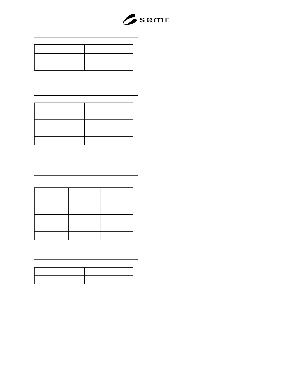
Table 3. Adhesive Material Thickness
Center Thickness t/
µ
m Tolerance/
µ
m
10.0 ≤ t < 14.0 ± 2.0
14.0 ≤ t < 20.0 ± 3.0
For thicknesses other than those above, use nominal value
thickness denoted in µm.
6.3.2 Adhesive Material Width (see Table 4)
Table 4. Adhesive Material Width
Width/mm Tolerance/mm
29.7
± 0.1
42.7
± 0.1
60.6
± 0.1
64.4
± 0.1
For widths other than those above, use nominal value width
denoted in mm.
6.4 Distance from Edge of Base Film to Edge of
Adhesive Material (see Table 5)
Table 5. Distance from Edge of Base Film to Edge
of Adhesive Material
Base Film
Width/mm
Adhesive
Material
Width/mm
Distance/mm
34.975 29.7
≥ 2.40
48.175 42.7
≥ 2.40
69.95 60.6
≥ 4.40
69.95 64.4
≥ 2.40
6.5 Cover Film Type, Thickness and Width
6.5.1 Cover Film Thickness (see Table 6)
Table 6. Cover Film Thickness
Thickness at Center/
µ
m Tolerance/
µ
m
10.0−50.0 ± 2.0
For thicknesses other than those above, use nominal value
thickness denoted in µm.
6.5.2 Cover Film Width — Use the same
measurements as found in Section 6.3.2.
6.6 Adhesive Tape Thickness and Tolerance
6.6.1 Adhesive Tape Thickness — Use the sum of the
nominal thicknesses of the base film, adhesive material
and cover film.
6.6.2 Tolerance — Use the sum of the nominal
tolerances of the base film, adhesive material and cover
film.
SEMI G76-0299 © SEMI 1999 3
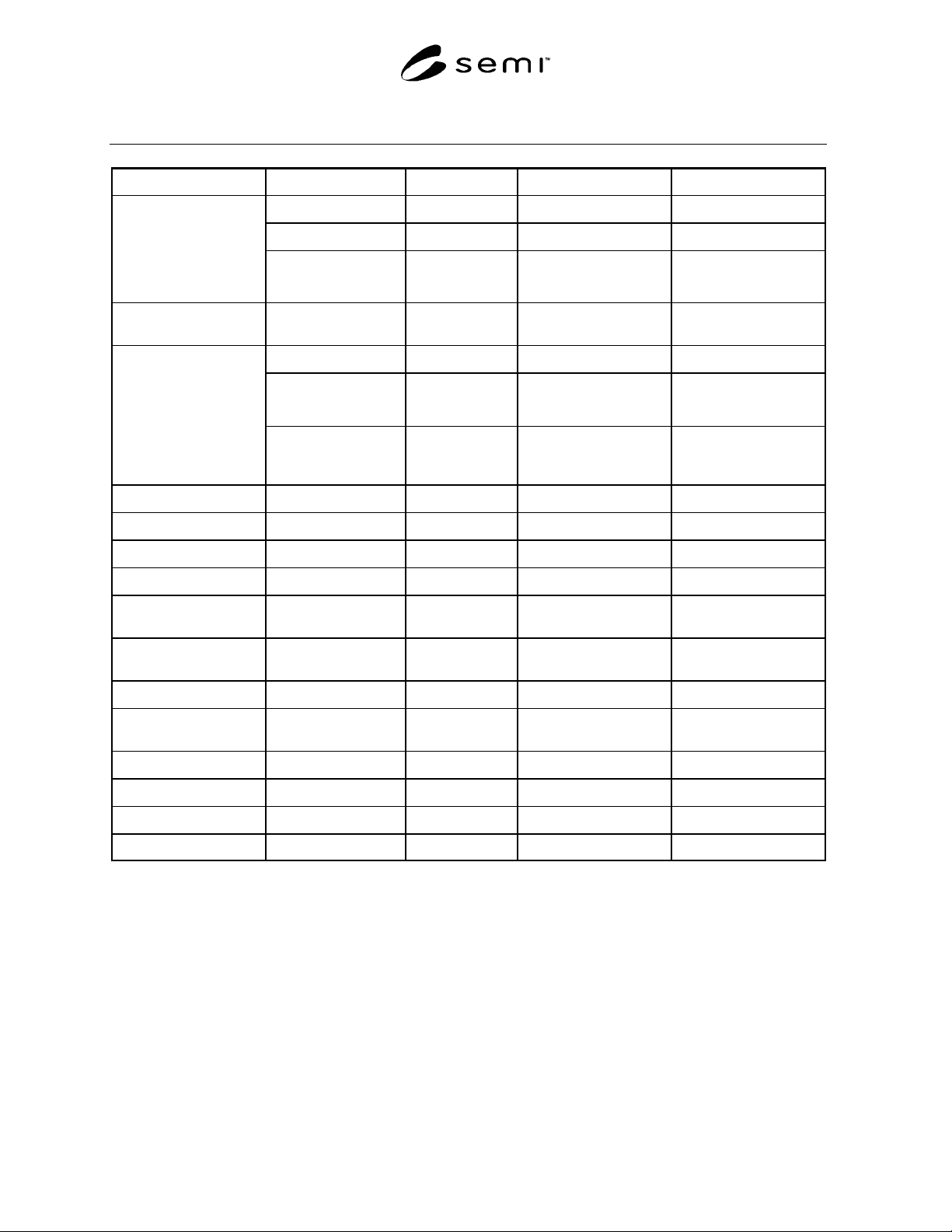
6.7 Characteristics (see Table 7)
Table 7. Characteristics of Adhesive Tape
Item Condition Unit Test Method Value
Normal N/cm 8.5.1 (a)
> 5
Heated N/cm 8.5.1 (b)
> 1
Copper Foil Adhesive
Strength
Soaked in solvent N/cm
(see NOTE 3)
8.5.1 (c)
> 3
Cover Film Release
Strength
Normal N/cm 8.5.2
< 0.2
Normal
Ω
8.6.3 (3)(a) Not Specified
In High Temp.
High Humidity
Ω
(see NOTE 4)
8.6.3 (3)(b) Not Specified
Insulation Resistance
In High Temp.
High Humidity,
Under Bias
Ω
(see NOTE 5)
8.6.3 (3)(c) Not Specified
Volume Resistivity Normal
Ω-cm
8.6.1
> 10
13
Surface Resistivity Normal
Ω
8.6.2
> 10
10
Voltage Resistance Normal
Ω
8.6.4 No Flash-over
Relative Permittivity Normal - 8.6.5
< 4.0
Dielectric Dissipation
Factor
Normal - 8.6.5
< 0.07
Solder Heat
Resistance
Normal - 8.7.1 No Delamination
No Swelling
Heat Shrinkage Normal % 8.7.3
< 0.5
Coefficient of
Thermal Expansion
-
cm/cm/°C
8.7.4
< 3.0 × 10
-5
Tensile Strength - Mpa 8.7.5
> 100
Elongation Normal % 8.7.5
> 20
Water Absorption Normal % 8.7.2
< 4.0
Flammability Normal - 8.7.6 Not Specified
NOTE 1: Normal Condition — Normal condition refers to a temperature of 23 ± 5°C, and relative humidity of 55 ± 15%.
NOTE 2: Heated Condition — See Section 8.5.1, (3)(b).
NOTE 3: Soaked in Solvent — See Section 8.5.1, (3)(c).
NOTE 4: High Temperature, High Humidity — See Section 8.6.3, (3)(b).
NOTE 5: High Temperature, High Humidity, Under Bias — See Section 8.6.3, (3)(c).
SEMI G76-0299 © SEMI 1999 4
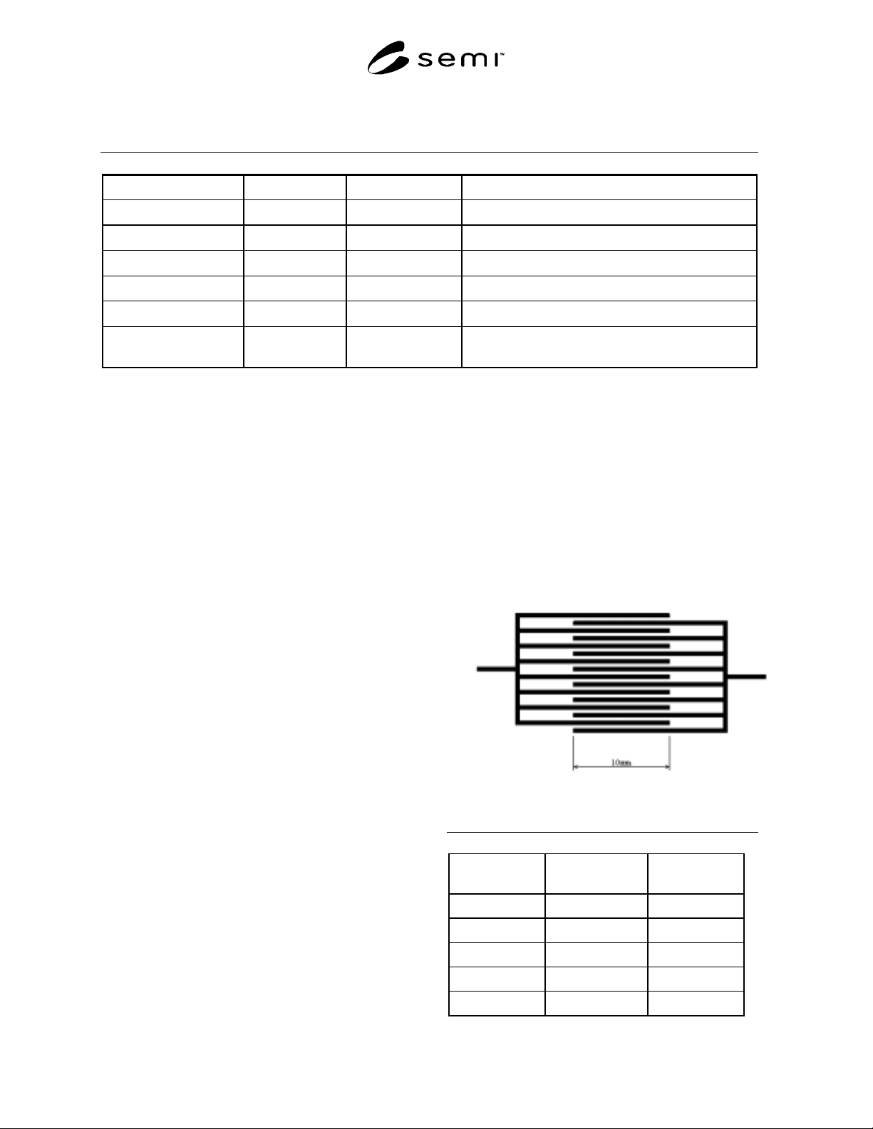
6.8 Appearance and Defects — See Table 8. Width and thickness for the base film, adhesive material and cover
film are not particularly specified.
Table 8. Appearance and Defects
Item Test Method Unit Value
MD Curl 8.8.1 mm
< 15
TD Curl 8.8.2 mm
< 6
Wakame 8.8.3 Number/m
< 20 of < 2 mm, 0 of > 2 mm
Camber 8.8.4 mm/m
< 1
Twist 8.8.5 Degrees
< 135
Defect 8.8.6 #/m or #/100m
< 5/m between 0.1 mm
2
and 1mm
2
or, < 10/100 m of > 1 mm
2
7. Sampling
A sampling plan shall be defined between the user and
supplier.
8. Test Methods
8.1 Test Conditions
8.1.1 Normal — Normal condition refers to a
temperature of 23 ± 5°C, and relative humidity of 55 ±
15%.
8.2 Materials
8.2.1 Material Preparation — Unless otherwise
specified, take the needed length of material from the
inner part of the roll after peeling off the first three
layers.
8.2.2 Lamination — Use the following steps to
prepare materials which require lamination:
(1) Material — Unless otherwise specified, use a
copper foil which has previously been decided
upon by the user and supplier.
(2) Lamination Method — Unless otherwise
specified, a method used shall be agreed
between user and supplier.
(3) Curing — Unless otherwise specified, a method
used shall be agreed between user and supplier.
8.2.3 Etching — For material which requires etching,
unless otherwise specified, a method used shall be
agreed between user and supplier.
8.2.4 Plating For material which requires plating,
unless otherwise specified, a method used shall be
agreed between user and supplier.
8.2.5 Test Pattern — The pattern used in Figure 1 is
recommended for the shape and dimensions of the test
pattern. Where this is not applicable, a pattern used
shall be agreed between user and supplier.
8.3 Pre-Conditioning — Unless otherwise specified,
leave the sample materials in normal condition for 24 ±
4 hours.
Figure 1
Test Pattern
Table 9. Test Pattern
Line Pitchs
(
µ
m)
Line Widths
(
µ
m)
Line Spacings
(
µ
m)
90 45 45
70 35 35
60 30 30
50 25 25
40 20 20