semi合集-English.pdf - 第673页
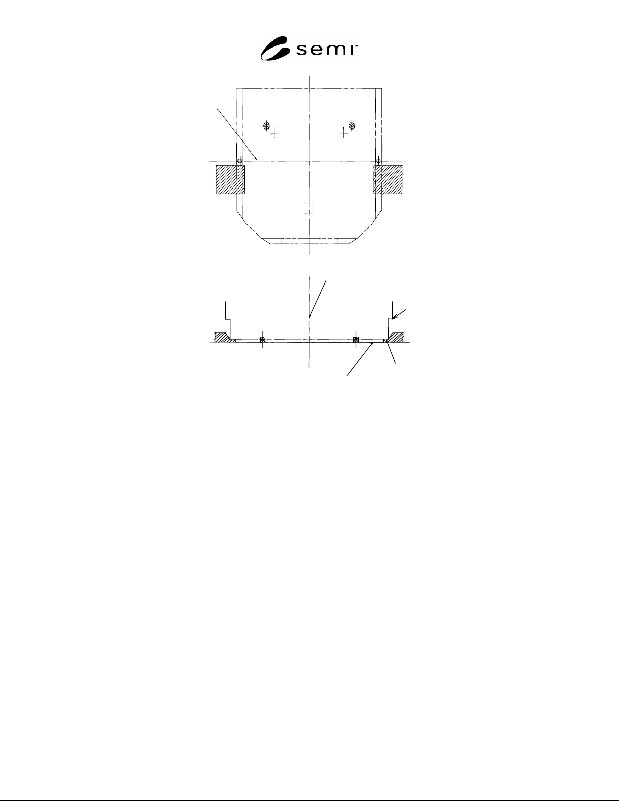
SEMI E85-0705 © SEMI 1999, 2005 27 Facial Datum Plan e Side rail Bottom rail FOUP Bilateral Datum Plane Horizontal Datum Plane Figure R1-3 A FOUP Example of Using Two Kinematic Coupling Pins, Part 2 NOTICE: SEMI makes no…
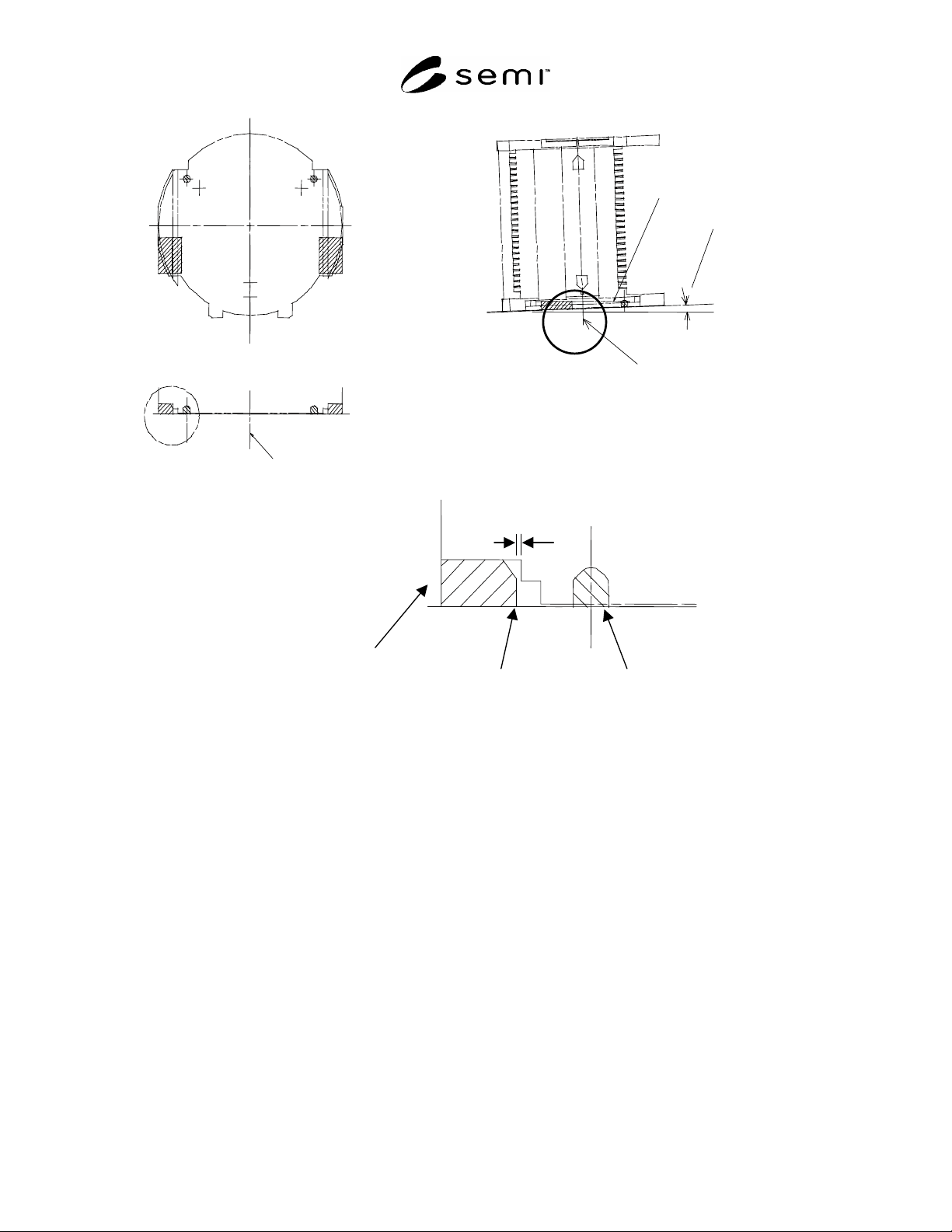
SEMI E85-0705 © SEMI 1999, 2005 26
Boundary of
cassette top
domain
Bilateral
Datum
Plane
A
Facial
Datum
Plane
Horizontal
Datum
Plane
Conveyor surface
2°
Horizontal
Datum
Plane
Lead-in
feature
Kinematic
coupling
p
in
Open Cassette
Detail A
Clearance
Figure R1-2
An Open Cassette Example of Using Two Kinematic Coupling Pins, Part 1
SEMI E85-0705 © SEMI 1999, 2005 27
Facial
Datum
Plane
Side rail
Bottom rail
FOUP
Bilateral Datum Plane
Horizontal Datum Plane
Figure R1-3
A FOUP Example of Using Two Kinematic Coupling Pins, Part 2
NOTICE: SEMI makes no warranties or representations as to the suitability of the standards set forth herein for any
particular application. The determination of the suitability of the standard is solely the responsibility of the user.
Users are cautioned to refer to manufacturer’s instructions, product labels, product data sheets, and other relevant
literature, respecting any materials or equipment mentioned herein. These standards are subject to change without
notice.
By publication of this standard, Semiconductor Equipment and Materials International (SEMI) takes no position
respecting the validity of any patent rights or copyrights asserted in connection with any items mentioned in this
standard. Users of this standard are expressly advised that determination of any such patent rights or copyrights, and
the risk of infringement of such rights are entirely their own responsibility.
Copyright by SEMI® (Semiconductor Equipment and Materials
International), 3081 Zanker Road, San Jose, CA 95134. Reproduction of
the contents in whole or in part is forbidden without express written
consent of SEMI.

SEMI E89-1104
E
© SEMI 1999, 2004 1
SEMI E89-1104
E
GUIDE FOR MEASUREMENT SYSTEM ANALYSIS (MSA)
This guide was technically approved by the Global Metrics Committee and is the direct responsibility of the
North American Metrics Committee. Current edition approved by the North American Regional Standards
Committee on August 16, 2004. Initially available at www.semi.org September 2004; to be published
November 2004. Originally published September 1999.
E
This standard was editorially modified in October 2004 to correct an editorial error in the title.
NOTICE: This document was completely rewritten in
2004.
1 Purpose
1.1 The purpose of this guide is to provide a consistent
set of terminology and describe a simplified, but
constructive, experimental approach to planning and
performing a measurement system analysis (MSA).
1.2 The goal of an MSA is to characterize the
performance capability of the measurement system
(MS) as it is intended to be used in a manufacturing or
laboratory setting.
1.2.1 Accurately identifying the MS bias and the size
and nature of all sources of variability allows one to
determine whether the MS is capable of performing its
intended function. Moreover, a well-designed MSA
can be used to identify and quantify areas that need the
most improvement.
2 Scope
2.1 This guide covers procedures for determining
specific measures of MS capability including:
measurement variability (i.e., reproducibility)
under a variety of conditions, including
effects of repeatability,
load-unload, and
time, and
bias, including bias-related
linearity,
stability, and
matching tolerance.
2.2 This guide also covers secondary metrics such as
precision-over-tolerance (P/T) ratio and signal-to-noise
ratio (SNR).
2.3 The primary focus of this guide is on determining
measurement capability of automated wafer MSs under
normal operating conditions, but the definitions and
methodologies are extendible to many other measure-
ment situations involving automated measurements on
units such as processed dice, packaged devices, flat
panel displays, piece parts, etc.
2.4 While there is no universally accepted correct way
to conduct an MSA, the approach described in this
document is supported in the technical literature (see
Section 11) and congruent with practices advocated in
ISO 5725-2. The procedures given in this guide
represent an approach to the conduct of an MSA and
provide basic reference methods that should serve for a
variety of applications. Other methods may be
appropriate in certain circumstances.
2.5 The procedures in this guide that are intended to
separate the various sources of nonsystematic (i.e.,
random) errors are based on the use of factorial
experiments and analysis of variance (ANOVA).
Because the primary focus of this guide is on evaluation
of automated MSs, the variability introduced by
different operators is expected to be minimal.
NOTE 1: Information on measurement uncertainty
calculations is provided in Related Information 1. Information
on testing measurement distributions for normality and equal
repeatability is provided in Related Information 2.
NOTICE: This standard does not purport to address
safety issues, if any, associated with its use. It is the
responsibility of the users of this standard to establish
appropriate safety and health practices and determine
the applicability of regulatory or other limitations prior
to use.
3 Limitations
3.1 Determination of MS capability is meaningless
unless the MS is in control. Methodology for
establishing and maintaining MS control is beyond the
scope of this guide. Such methodology should be a part
of a quality management system, such as that mandated
by ISO 9000 or similar standards. Additional guidance
for laboratories without established procedures may be
found in the ASTM Manual on Presentation of Data
and Control Chart Analysis.
1
1 Manual on Presentation of Data and Control Chart Analysis, 6th
edition, MNL 7 (ASTM International, West Conshohocken, PA,
1991)