semi合集-English.pdf - 第6813页
SEMI S2-0703a E © SEMI 1991, 2004 42 APPENDIX 4 IONIZING RADIATION TEST VALI DATION — Design and Test Method Supplement Intended for Internal and Third Party Evaluation Use NOTICE : The material in this appendix is an of…
SEMI S2-0703a
E
© SEMI 1991, 2004 41
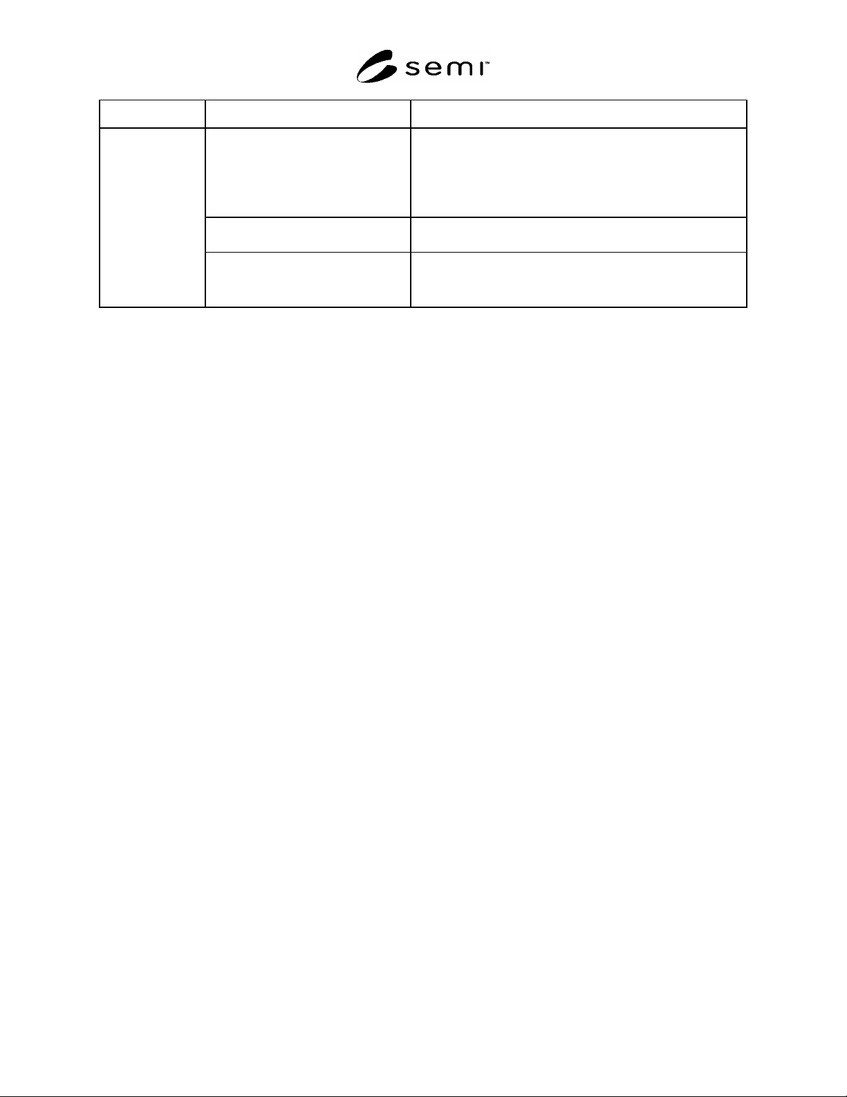
Potential Hazard Recommended Control Method Design Considerations
Control of ignition sources.
NFPA 70 (NEC) Class I, Div. 2 wiring methods, intrinsically
safe components, or nitrogen-purged enclosures
Physical separation of ignition sources and/or potentially
flammable atmospheres.
Use of low voltage to reduce the risk for ignition.
Control of static electricity (i.e., one
type of ignition source).
Maintain ground continuity
Fire
Heat/fire/chemical detection
Limiting concentrations of fuels and
oxidizers.
(No consensus for a specific recommendation at the time of
publication of this guideline.)
SEMI S2-0703a
E
© SEMI 1991, 2004 42
APPENDIX 4
IONIZING RADIATION TEST VALIDATION — Design and Test Method
Supplement Intended for Internal and Third Party Evaluation Use
NOTICE: The material in this appendix is an official part of SEMI S2 and was approved by full letter ballot
procedures on December 15, 1999 by the North American Regional Standards Committee.
A4-1 Introduction
A4-1.1 This appendix provides specific technical information relating to Section 24. In general, it provides
information on hazard evaluation methods, examples of control strategies, and test validation criteria.
A4-1.2 This appendix is not intended to limit hazard evaluation methods or control strategies (e.g. design
principles) employed by the manufacturers. Alternative methods are acceptable if they provide an equivalent level of
hazard control.
A4-1.3 Test validation criteria are generally referenced from the applicable internationally recognized standard. It is
the users responsibility to ensure that the most current revision of the standard (or its national equivalent) is used.
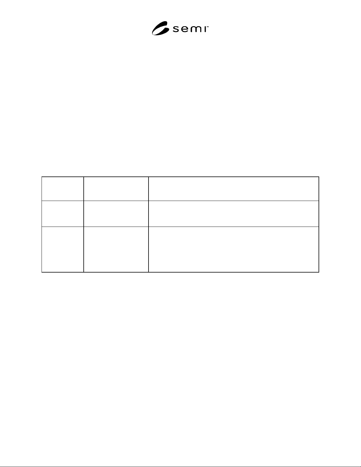
Table A4-1 Ionizing Radiation
Ionizing
Radiation Type
Emission Limit
microsievert/hr
(millirem/hr)
Test Method
X or Gamma Operator
2 Sv/hr
(0.2 mrem/hr)
Direct doserate measurement with an Ion Chamber (or equivalent) calibrated
to ± 10% of true doserate at the surface of the equipment (or at the closest
approach) in all areas where the operator may have access with the ionizing
radiation source active.
X or Gamma Maintenance and Service
10 Sv/hr
(1 mrem/hr)
Direct doserate measurement with an Ion Chamber (or equivalent) calibrated
to ± 10% of true doserate during simulated maintenance and service
procedures. Measurements should be made at the surface emitting the
ionizing radiation or the closest approach to the emitting surface with the
ionizing radiation source active.
NOTE: For these measurements, panels and/or shields should be removed
only if removal is required for maintenance or service activities.
A4-2 Basic Radiation Control Methods
Time — If the radiation field exists and it must be entered, then minimize the time spent in the field to minimize the
exposure to the individual. This gives a linear dose reduction.
Distance — If the radiation field is present, stay as far away form the source as possible to perform the required
tasks. Dose is reduced by the square of the distance from the source.
Shielding — If the radiation field is intense and the source is small, shielding the source is generally the most
practical.
Quantity — If there exists an opportunity to minimize the amount of radiation or radioactive material that is required
for the task, then the exposure can be minimized also.
SEMI S2-0703a
E
© SEMI 1991, 2004 43
APPENDIX 5
NON-IONIZING RADIATION (OTHER THAN LASER) AND FIELDS TEST
VALIDATION — Design and Test Method Supplement Intended for
Internal and Third Party Evaluation Use, But Not for Field Survey of
Installed Equipment
NOTICE: The material in this appendix is an official part of SEMI S2 and was approved by full letter ballot
procedures on December 15, 1999 by the North American Regional Standards Committee.
A5-1 Introduction
A5-1.1 This appendix provides specific technical
information relating to Section 25. In general, it
provides information on hazard evaluation methods and
test validation criteria.
A5-1.2 This appendix is not intended to limit hazard
evaluation methods or control strategies (e.g., design
principles) employed by manufacturers. Alternative
methods are acceptable if they provide an equivalent
level of hazard control.
A5-1.3 Test validation criteria are generally referenced
from the applicable internationally recognized
standards. It is the user’s responsibility to ensure that
the most current revision of the standard is used.
A5-2 Non-Ionizing Radiation Surveys should be
conducted at the maximum operational power level and,
when applicable, at the most limiting frequency.
A5-3 Measurements should be taken at the exterior
surfaces of the equipment and at surfaces that
maintenance and repair personnel could encounter,
whenever practical (electric field measurements with
paddle-shaped sensors may not be possible in some
places due to the size and shape of the sensor).
Measurements for the purpose of evaluating emissions
accessible to operators should be taken at the operators
console and material loading station.
A5-4 Measurements to assess electromagnetic
emissions from equipment for safety purposes should
be taken in an area that is reasonably free of energy of
the wavelengths/frequencies of interest, especially if the
strength of the energy fluctuates in a manner that is
unpredictable. Instruments used for safety-related
measurements should be calibrated at a facility capable
of calibrating such instruments using standards
traceable to the National Institute of Standards and
Technology in the USA or an equivalent standards
service elsewhere, per the guidance of the instrument
manufacturer. This should be determined by conducting
surveys in the test area before the equipment is set up
for the measurements. Measurements taken for safety
purposes can also be combined with measurements
taken to address electromagnetic interference concerns.
The specific measurement locations may vary between
electromagnetic interference and safety-related
measurements.
NOTE A5-1: The values in the table below are shown as 20%
of the limit stated in the applicable standard (referenced).
Table A5-1 Non-Ionizing Radiation
Energy
Category
Physical
Quantity
Measured
(units)
Operator-
Accessible Limit
Maintenance-
and Service-
Accessible Limit
Pacemaker
Labeling
Level
Testing Methods
Static
4
0 Hz.
(e.g., static
magnets in
etch/implant
equipment)
Magnetic
Field
Strength
(A/m or
Gauss)
(See
NOTES 1
and 2.)
8 mT
(80 G)
40 mT
(400 G)
0.5 mT
(5 G)
Use a Hall effect probe at each
location (use three axis probe or
make three mutually orthogonal
measurements at each location).
Measure field at exterior surfaces
of equipment (2 to 3 cm from the
surface). Locate 5 gauss (G) line
to post pacemaker warnings and
30 G to identify where flying
tools, etc. and dislocations of
magnetizable prostheses could
become a hazard.