semi合集-English.pdf - 第6835页
SEMI S2-0703a E © SEMI 1991, 2004 64 DESIGN EXAMPLE (continued; refer to Figu re R5 -1 for illustration of example) Disclaimer: the calculations below are not a complete seismi c analysis. A com p lete analysis might als…
SEMI S2-0703a
E
© SEMI 1991, 2004 63
L1
L2
A
h
A
A
R
L3
A B
VIEW A – A
F
p(x)
CG
F
p(y)
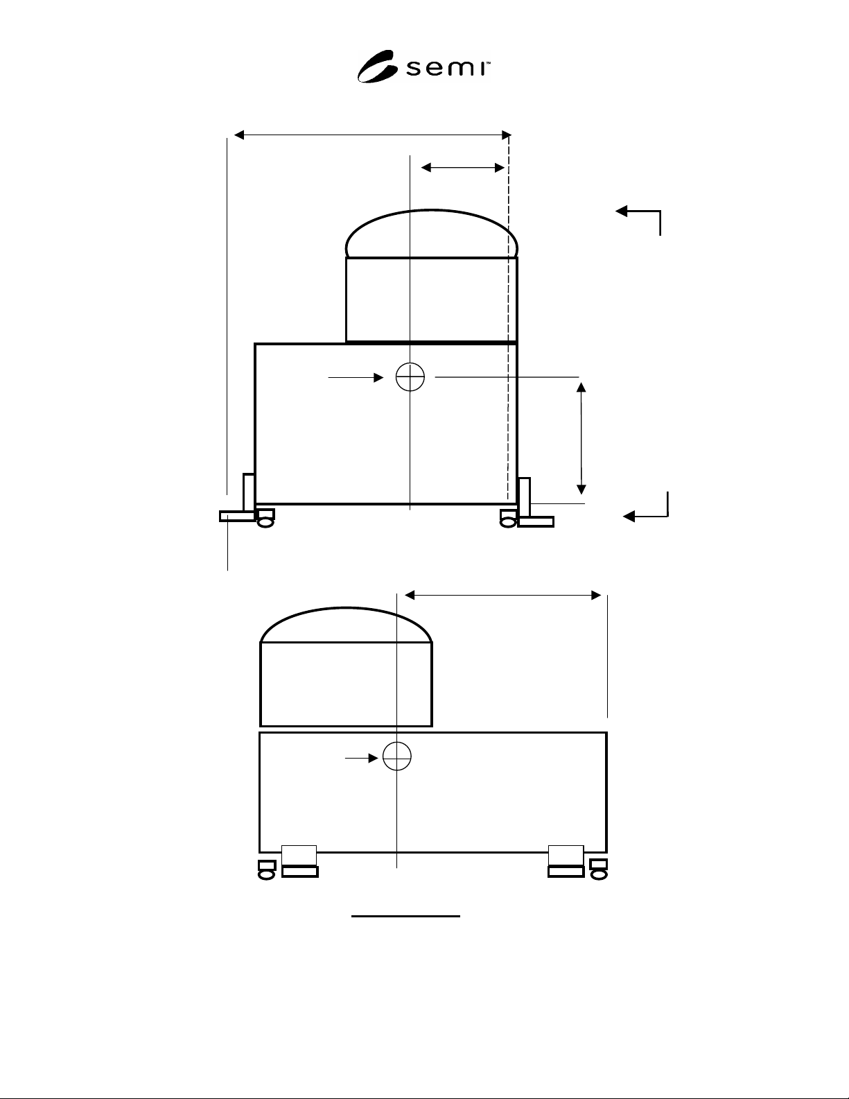
Figure R5-1
Design Example

SEMI S2-0703a
E
© SEMI 1991, 2004 64
DESIGN EXAMPLE (continued; refer to Figure R5-1 for illustration of example)
Disclaimer: the calculations below are not a complete seismic analysis. A complete analysis might also include such
things as: stress distribution through a multiple-fastener connection; prying action; bearing stress; simultaneous
combined stresses on the fasteners; and a review of weld geometry. A complete seismic analysis should be done by
a qualified engineer.
R5-4 Calculation of Lateral Force
R5-4.1 Lateral force on each leg is equal to F
P
/# of legs = F
P
/4
R5-4.2 The lateral force acts as shear on the floor anchor fasteners and shear or tensile loading on the equipment
anchor fasteners depending upon orientation. The actual reactions of the fasteners should be calculated by a
qualified engineer.
R5-5 Calculation of Overturning Force
R5-5.1 Sum the moments of the reactions on the system about line through the legs A and B:
(CW =+) M
AB
= 0 = F
P
(h) – 0.85W
P
(L
2
) –2R(L
1
)= 0
F
P
(h) – 0.85W
P
(L
2
)
R = _________________
2L
1
F
P
= 0.94W
P
W
P
(0.94h – 0.85L
2
)
R = _________________
2L
1
If 0.94h
0.85L
2
, then there is a tension reaction, R, at the two anchors, to resist overturning of system.
Example:
L1 = 50 inch
L2 = 20 inch
h= 36
W = 5000 lbs
Lateral force
= Fp/4 = 0.94(5000)/4 = 1175
W
P
(0.94h – 0.85L
2
)
Overturning force
= R =_________________
2L
1
= 5000 (0.94(36) – 0.85(20))
_____________________
2(50)
R = 842 lbs
SEMI S2-0703a
E
© SEMI 1991, 2004 65
RELATED INFORMATION 6
CONTINUOUS HAZARDOUS GAS DETECTION
NOTICE: This related information is not an official part of SEMI S2 and was derived from practical application by
task force members. This related information was approved for publication by vote of the responsible committee on
October 21, 1999.
R6-1 Scope — This related information provides a list
of gases for which continuous monitoring is
recommended, and another list of gases for which
continuous monitoring may be recommended
depending on variables listed below. The list is not
intended to be exhaustive (gases that do not appear on
the list may need to be continuously monitored).
R6-2 Intent — The purpose of this Related Information
is to provide equipment manufacturers with an
indication as to what gases are currently continuously
monitored by device manufacturers, as guidance for
when it may be appropriate to provide an interface (see
also Section 23).
R6-3 The following variables should be taken into
consideration when determining the necessity for
continuous monitoring:
Chemical toxicity,
Warning property/OEL ratio,
Delivery pressure,
LEL,
Flow rate of potential leak,
Engineering controls in place, and
Concentration.
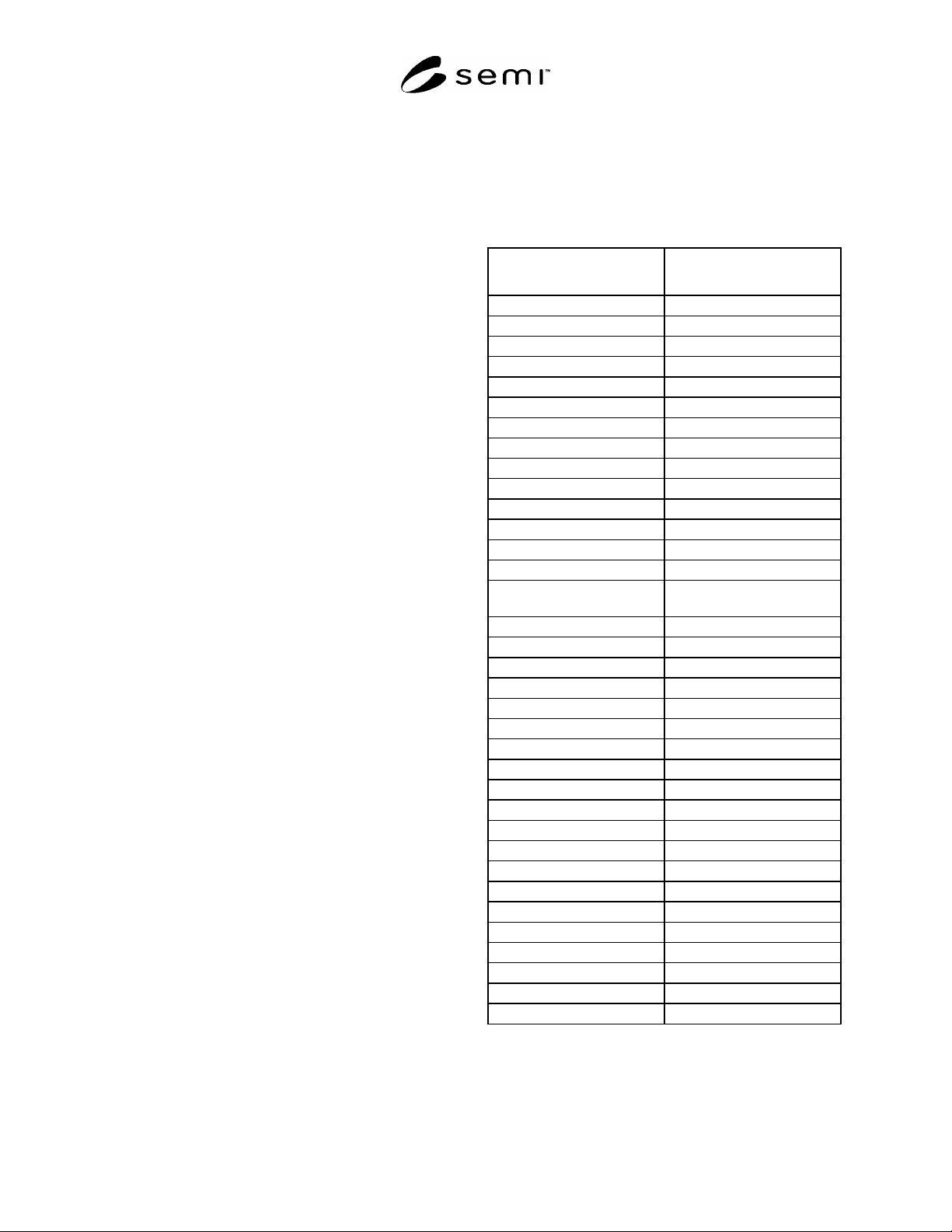
Monitoring Recommended Monitoring May Be
Recommended
ammonia
arsine
boron trifluoride
bromine
carbon dioxide
carbon monoxide
carbon tetrabromide
chlorine
diborane
dichlorosilane
disilane
fluorine
germane
germanium tetrafluoride
flammable mixtures
containing hydrogen
hydrogen bromide
hydrogen chloride
hydrogen fluoride
hydrogen selenide
hydrogen sulfide
Methane
methyl chloride
methyl fluoride
nitric oxide
nitrogen dioxide
nitrous oxide
nitrogen trifluoride
ozone
phosphine
silane
silicon tetrachloride
silicon tetrafluoride
sulfur dioxide
trichlorosilane
tungsten hexafluoride