semi合集-English.pdf - 第714页
SEMI E99-1104 E © SEMI 2000, 2004 4 6.3.4 Service Message Definition 6.3.4.1 A service message defini tion table de fines the paramete rs used in a service, as s hown in the followi ng table: Parameter Req/Ind Rsp/Cnf Co…

SEMI E99-1104
E
© SEMI 2000, 2004 3
6.1.2 Transition tables are provided in conjunction with the state diagrams to explicitly describe the nature of each
state transition. A transition table contains columns for Transition number, Previous State, Trigger, New State,
Actions, and Comments. The “trigger” (column 3) for the transition occurs while in the “previous” state. The
“actions” (column 5) includes a combination of:
Actions taken upon exit of the previous state.
Actions taken upon entry of the new state.
Actions taken which are most closely associated with the transition.
6.1.2.1 No differentiation is made between these cases.
6.2 Object Notation
6.2.1 The object models in Related Information 2 use the Object Modeling Technique (OMT) developed by
Rumbaugh, James, et al, in Object-Oriented Modeling and Design.
2
An overview of this notation is provided in
SEMI E39, Object Services Standard: Concepts, Behavior, and Services.
Num Previous State Trigger New State Actions Comments
6.3 Service Message Representation
6.3.1 Services are functions or methods that may be provided by either the equipment or the host. A service
message may be either a request message, which always requires a response, or a notification message, that does not
require a response.
6.3.2 Service Definition
6.3.2.1 A service definition table defines the specific set of messages for a given service resource, as shown in the
following table:
Message Service Name Type Description
Type can be either “N” = Notification or “R” = Request & Response.
6.3.2.2 Notification type messages are initiated by the service provider (e.g., the equipment) and the provider does
not expect to get a response from the service user. Request messages are initiated by a service user (e.g., the host).
Request messages ask for data or an activity from the provider. Request messages expect a specific response
message (no presumption on the message content).
6.3.3 Service Parameter Dictionary
6.3.3.1 A service parameter dictionary table defines the description, format and its possible value for parameters
used by services, as shown in the following table:
Parameter Name Description Format: Possible Value
6.3.3.2 A row is provided in the table for each parameter of a service.
2 James Rumbaugh, Michael Blaha, William Premerlani, Frederick Eddy, William Lorensen, Object-Oriented Modeling and Design
, Englewood
Cliffs, New Jersey: Prentice-Hall, 1991.
SEMI E99-1104
E
© SEMI 2000, 2004 4
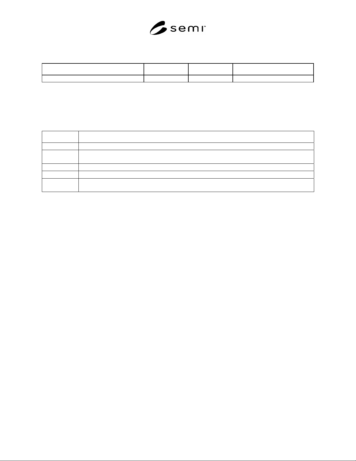
6.3.4 Service Message Definition
6.3.4.1 A service message definition table defines the parameters used in a service, as shown in the following table:
Parameter Req/Ind Rsp/Cnf Comment
6.3.4.2 The columns labeled REQ/IND and RSP/CNF link the parameters to the direction of the message. The
message sent by the initiator is called the “Request”. The receiver terms this message the “Indication” or the request.
The receiver may then send a “Response” which the original sender terms the “Confirmation”.
6.3.4.3 The following codes appear in the REQ/IND and RSP/CNF columns and are used in the definition of the
parameters (e.g., how each parameter is used in each direction):
Code Description
M Mandatory Parameter — Must be given a valid value.
C Conditional Parameter — May be defined in some circumstances and undefined in others. Whether a value
is given may be completely optional or may depend on the value of the other parameter.
U User-Defined Parameter.
- The parameter is not used.
= (For response only.) Indicates that the value of this parameter in the response must match that in the primary
(if defined).
7 Overview
7.1 The Carrier ID Reader/Writer Model defines the behavior and services (functions) for both Carrier ID Readers
and Carrier ID Reader/Writers. The Carrier ID Reader/Writer is a small intelligent system, typically used as a
subsystem within equipment.
7.1.1 The primary functionality of the Carrier ID Reader/Writer is to read the identifier of the carrier (Carrier ID)
from the Carrier ID tag. Various technologies may be used to encode the Carrier ID and to read it. Some
technologies do not allow data to be written.
7.1.2 The acronym CIDRW is used to refer to both the Carrier ID Reader and the Carrier ID Reader/Writer. The
requirements for the Carrier ID Reader are a subset of the requirements for the Carrier ID Reader/Writer.
7.1.3 An object model for the CIDRW is provided in Related Information 2 – Object Model.
7.2 Number of Heads
7.2.1 A Reader/Writer Head is a device that is positioned on a load port for reading or reading/writing information
from a Carrier ID tag. A Carrier ID Reader/Writer provides one or more ID Reader/Writer Heads and is connected
to an upstream controller by a single interface. This allows the upstream controller to control either one head or
multiple heads using the same interface specification.
7.2.2 Single Head Configuration
7.2.2.1 In the case of a single head, the head may be presented as an integrated part of the CIDRW.
7.2.3 Multiple Head Configuration
7.2.3.1 In the case of multiple heads, some services are logically performed by the CIDRW, and the individual
heads logically perform others. The individual heads are numbered sequentially and may be referenced individually
by the upstream controller. Note that the upstream controller does not communicate directly with the heads. All
communications are between the upstream controller and the CIDRW unit.
7.2.3.2 In the multi-head case, the CIDRW shall allow independent control of the heads. Multiple transactions
invoking services performed by the individual heads may be open at the same time. For example, when a read
command is sent to one head, the host can send additional commands such as a read command and a status
confirmation command to another head before the first head sends the response to the first command.

SEMI E99-1104
E
© SEMI 2000, 2004 5
7.3 Upstream Controller
7.3.1 The CIDRW provides certain services when requested by the upstream controller. The upstream controller
sends a message requesting the specified service, and the CIDRW sends a message with the response.
7.3.2 This standard assumes that an upstream controller initiates each service message to the CIDRW, and the
CIDRW sends its response to the upstream controller. The upstream controller must watch the response time to
monitor the communication timeout. This standard will define the recommended method for handling exceptions
caused by timeouts.
7.3.3 In addition, some CIDRW may provide asynchronous notification to the upstream controller. Examples of this
include, but are not limited to, the detection of a fault condition resulting in an alarm. Asynchronous notification is
not required for compliance to this standard.
8 Attributes
8.1 An attribute is an item of information about an entity that is maintained and is available by request. There is
certain information concerning the CIDRW that is of potential interest to the upstream controller, including the
manufacturer, the model, and the serial number of the device. This information is considered as attributes of the
CIDRW and is available on request.
8.2 CIDRW Attribute Definition Table
8.2.1 Table 1 defines the attributes of the Carrier ID Reader/Writer subsystem.
Table 1 CIDRW Attribute Definitions
Attribute Name Description Access Reqd Form
Fundamental
Configuration Number of heads. RO Y Text
Alarm Status Current CIDRW substate of ALARM
STATUS.
RO Y Enumerated:
0 = NO ALARMS
1 = ALARMS
Operational Status Current CIDRW substate of
OPERATIONAL.
RO Y Enumerated:
IDLE
BUSY
MAINTENANCE
SoftwareRevisionLevel Revision (version) of software. RO Y Text
Optional
CarrierIDOffset
Offset position of the first byte for Carrier
ID in the Electric Tag.
RW N 00-15
CarrierIDLength
Length byte of the Carrier ID.
If non-visible ASCII character exists in
this string, CIDRW shall send out an error
to the upstream controller.
RW N 01–16
DateInstalled Date the subsystem was installed. RO N Protocol dependent.
Device Type Identifiers subsystem as either a Carrier ID
Reader or a Carrier ID Reader/Writer.
RO N Text
HardwareRevisionLevel Revision number of the hardware. RO N Text
MaintenanceData Supplier dependent. RO N Text
Manufacturer The name or identifier of the manufacturer. RO N Protocol dependent.
ModelNumber The manufacturers model designation. RO N Text
SerialNumber Subsystem serial number assigned by
manufacturer.
RO N Protocol dependent.