semi合集-English.pdf - 第7141页
SEMI S22-1103a © SEMI 2003, 2005 26 17.1.2 The installation of flexible conduits and cab les should be such that liquids drain away from the fittings. 17.1.3 Terminal block s should be m ounted and wired so that the int …

SEMI S22-1103a © SEMI 2003, 2005 25
16.2.2 Printed Circuit Boards Printed wire assemblies of flame-retardant material should be allowed in place of
conductor assemblies provided that they are within electrical enclosures and are mounted in such a way as to
minimize flexing or stress. All printed circuit boards should have a flammability rating of V-1 or better (See IEC
60707 or UL 94); or a rating of FR-4 or FR-5 (ANSI/IPC 2221).
16.2.3 Bus Bars Non-insulated bus bars should be sized according to Appendix 1, Table A1-7.
16.2.4 Insulation The insulation on each conductor should be rated to take into account:
a) the electrical, thermal and mechanical strength for the maximum voltages and currents that can be applied to
the conductor,
b) the worst environment (e.g., temperature, pressure, humidity, vibration and pollution) where the conductor
may be routed, and
c) resistance to flame spread.
16.2.5 Natural rubber and materials containing asbestos should not be used as insulation.
16.2.6 Hazards Associated with Insulation
Where the insulation of conductors and cables can constitute hazards
due to the propagation of fire or the emission of toxic or corrosive fumes under single fault conditions, additional
protections should be provided or alternative conductor or cable assemblies should be considered.
16.2.7 Dielectric Strength of Wire and Cable Insulation A test mark from an accredited testing laboratory on the
wire or cable may be used to demonstrate suitability of the wire when it is used in accordance with its voltage rating.
An alternate means of compliance can be obtained by the test described below. Cables and wires operating at a
nominal voltage of higher than 50 V AC or 120 V DC should withstand a dielectric test voltage of 1000 V plus two
times their working rated voltage or 2000 V AC for 5 minutes, whichever is higher. This test for dielectric
breakdown should be applied between the wire or cable conductor and foil wrapped around the conductor insulation.
16.2.8 Insulation Strength The mechanical strength and thickness of the insulation should be such that the
insulation cannot be damaged in normal operation or as a result of reasonably foreseeable abuse, so as to fail to
provide adequate protection.
16.3 Flexible Cables
16.3.1 Flexible cords, cables and power cord sets are permitted inside electrical enclosures for internal wiring:
a) when equipped with an attachment plug and powered from a receptacle outlet inside the electrical enclosure to
connect one or more assemblies to primary power inside the enclosure; and
b) when the insulation on the individual conductors of the flexible cord or cable are suitable for the application
without consideration of the outer jacket insulation; and
c) when the AC flexible cord, AC power cord set, AC receptacles, and AC appliance coupler are all used in
accordance with their ratings.
NOTE 46: Power cord sets are preferred over non-detachable cords to facilitate replacement of assemblies without modifying or
removing the flexible cord.
16.3.2 Exposed flexible cords and cables installed along the structure of the equipment or system or in the chassis
of the machinery is allowable when they are not subject to physical damage from normal operations. Exposed
cables should be installed to closely follow the surface and structural members of the machinery.
17 Wiring Practices
17.1 Connections and Routing
17.1.1 All connections should be secured against accidental loosening. Terminals should be sized appropriately for
the conductors that are being terminated. The connection of two or more conductors to one terminal is allowable
only where the terminal is designed and identified for that purpose. All soldered connections should be
mechanically secured before soldering. Terminals on terminal blocks should be clearly identified to correspond with
markings on the diagrams, or terminal identification should be provided in system manuals or another equivalent
means of identification should be provided.
SEMI S22-1103a © SEMI 2003, 2005 26
17.1.2 The installation of flexible conduits and cables should be such that liquids drain away from the fittings.
17.1.3 Terminal blocks should be mounted and wired so that the internal and external wiring does not cross over the
terminals.
17.1.4 Conductors and cables should be connected from terminal to terminal without splices.
17.1.5 Where circuits operate at different voltages, the conductors of each voltage level should be separated by
suitable barriers, or routed separately and secured, or all conductors grouped or bundled together should be insulated
for the highest voltage present in the group or bundle.
17.1.6 Conductors smaller than 1/0 AWG should not be connected in parallel to the same terminations to attain the
necessary ampacity.
17.1.7 Conductors should not be exposed to temperatures greater than their temperature rating. If the wire
termination has a lower temperature rating than the conductor, the lower temperature rating should be used to
evaluate the suitability of the conductor.
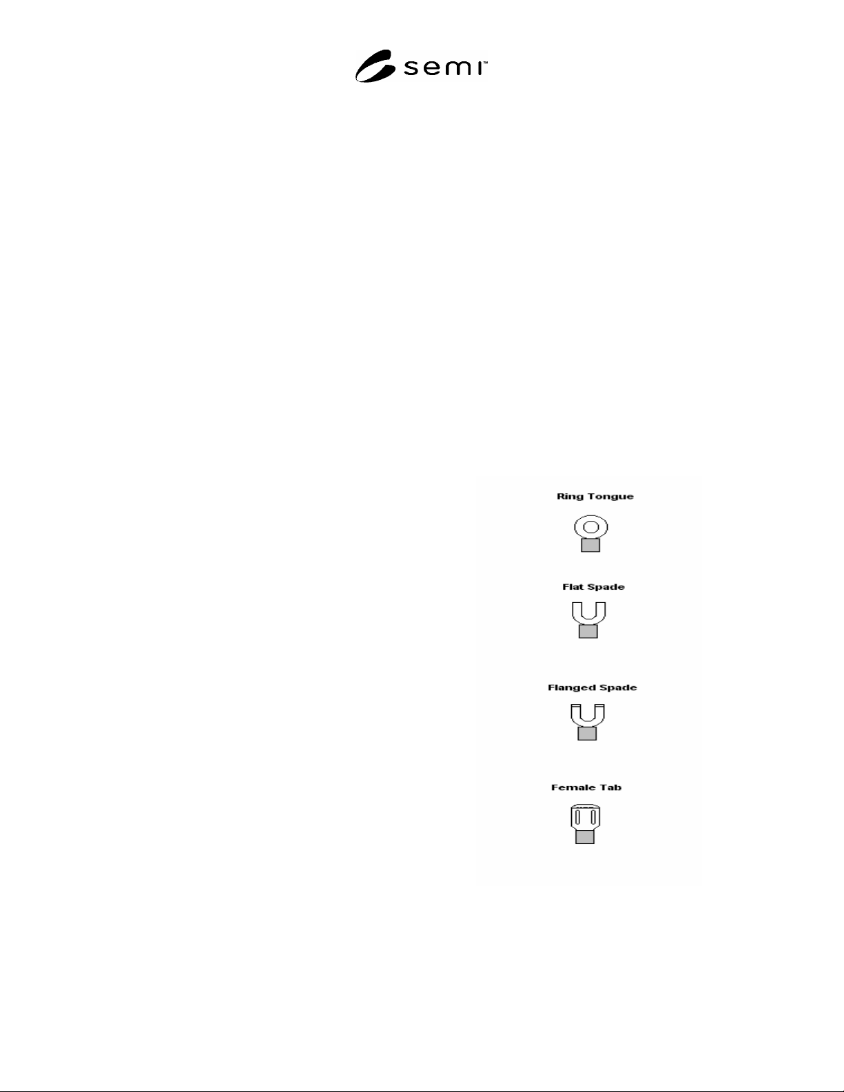
17.2 Terminal Lugs Terminal lugs should be utilized according to the following:
a) Ring Tongue Desired for all terminations not routinely disconnected for access and service;
b) Flat Spade not desired for terminating hazardous potentials or hazardous energy levels and not suitable for
bonding or earthing (grounding).
c) Flanged Spade not desired for earthing except on a captive screw;
d) Female Tab
Desired only for terminations to fixed male tabs on components or panels.
17.3 Attachment Plugs, Cord Connectors, and
Receptacles If an unacceptable risk can result from
misconnection, then receptacles and cord connectors
should not accept an attachment plug with a different
voltage or current rating.
17.3.1 Only female cord connectors should be used to
supply power.
17.3.2 Receptacles should be rated for at least 125
percent of the maximum rated design load (current)
intended for the circuit.
17.3.3 Each receptacle should be individually bonded
to the protective earthing system.
17.3.4 Series connection of the protective conductor
from receptacle to receptacle should not be used.
17.3.5 Convenience receptacles accessible from the
exterior of the equipment should be protected by a
ground-fault circuit-interrupter (GFCI).
NOTE 47: A receptacle that is used to supply power to a
subsystem is not a convenience receptacle.
17.4 Temporary Power Taps Temporary power taps
(commercial power strips) should not be used for
installation in or on equipment.
EXCEPTION: Permanently installed fixed power strips
that are suitable for industrial equipment are acceptable
if they have been evaluated by an accredited testing
laboratory for this application.
Figure 1
Terminal Lugs

SEMI S22-1103a © SEMI 2003, 2005 27
17.5 Multi-Outlet Assemblies Multi-outlet power assemblies should:
a) contain receptacles suitable for commercial or industrial application, and
b) be a minimum size of 70 mm (2.75 in.) by 36.6 mm (1.44 in).
17.6 Identification of Conductors
17.6.1 Each conductor should be identified by a number, letter, color, a combination of the above or other scheme
consistent with the product documentation.
17.6.2 Where color is used for the sole means of identification, it is acceptable to apply appropriate colored tape or
sleeve at the conductor ends. The tape or sleeve should be wrapped around, or otherwise reliably secured to, the
conductor.
17.6.3 Identification of the Protective Conductor Electrical wiring for protective conductors should be labeled
for easy identification at both ends of the wire. The protective conductor should be readily distinguishable by shape,
location, marking, or color.
17.6.3.1 When color alone is used to identify the protective conductor, the bicolor combination green and yellow
should be used throughout the length of the conductor. The bicolor combination green and yellow should be such
that on any 15 mm length, one of the colors covers at least 30 percent and not more than 70 percent of the surface of
the conductor with the other color covering the remainder of the surface.
EXCEPTION: Solid green can be used to identify protective conductors if the documentation describes this means
of identifying protective earth.
17.6.3.2 Green and yellow or green alone should not be used to identify any other conductor.
17.6.4 Identification of the Earthed (Neutral) Conductor Where color alone is used to identify the earthed
(neutral) conductor, white or gray should be used.
EXCEPTION: Light blue will be acceptable if the earthed (neutral) conductor is identified by an additional means.
NOTE 48: Light blue may not be accepted in some jurisdictions.
17.6.4.1 White, gray, and light blue should not be used to identify any other conductors.
17.6.5 Identification of Other Conductors Where color alone is used to identify other conductors, black should
be used for all unearthed AC and DC power circuits.
17.7 Wiring Inside Electrical Enclosures
17.7.1 Wiring that carries hazardous voltage located inside enclosures should be securely routed to avoid
mechanical abuse during maintenance or troubleshooting.
17.7.2 Wiring should be protected from contact with liquids that may be present under reasonably foreseeable
single fault conditions, unless the wiring is suitably rated for a wet environment.
17.7.3 Wires should be routed away from sharp edges or surfaces that may degrade their insulation.
17.7.4 Wire guides may be used for wire routing. However, these guides should be constructed so as not to
adversely affect the insulation of the wires they secure.
17.8 Wiring Outside Electrical Enclosures
17.8.1 Conductors external to the electrical enclosure(s) should be enclosed in suitable ducts, raceways, or run in
suitable multi-conductor cable. Fittings used with ducts, raceways, or multi-conductor cable should be suitable for
the anticipated physical environment. Cables should not be subjected to physical stress (e.g. pinching, crushing, foot
traffic, or abrasion).
17.8.2 Flexible conduit or flexible multi-conductor cable should be used where it is necessary to employ flexible
connections to pendant push-actuator stations. The weight of the pendant stations should be supported by means
other than the flexible conduit or the flexible multi-conductor cable, except where the conduit or cable is specifically
designed for that purpose.