semi合集-English.pdf - 第7180页
SEMI S23-0705 © SEMI 2005 13 Example Calcul ation (idling) for Rec ipe “X” Electricity Mean real power = 4.16E + 1 kW Heat Input per Year = 4 .16E + 1 kW × 2190 hr = 9.11E + 4 kWh ( no other heat input sources) Air Exhau…
SEMI S23-0705 © SEMI 2005 12
removed per year by cooling water in a similar manner, using the “Removal via Water” conversion factor. Finally
subtract the last two energy values from the first to get the heat load of the equipment that is transferred to the room
in which the equipment resides.
R1-2.6.6 Once the room heat load of the equipment has been estimated, the “Heat Load Burden” conversion factor
can be used to express the energy required to remove that heat from the equipment environment.
R1-2.7 Electrical Energy
R1-2.7.1 A conversion factor of 1 is presented for electrical energy. The value thus calculated is the electrical
energy supplied to the equipment.
R1-2.7.2 The amount of energy required to generate the electricity is not addressed by this conversion factor of 1.
This additional detail may be useful, but the applicable conversion factor will depend on the technologies used to
generate and distribute the electricity that is used.
NOTE 2: For example, the energy content of coal is approximately 8000 kWh per ton. If the electricity provider must burn one
ton of coal to generate 6000 kWh of electrical energy, the electrical energy conversion factor could be set to 1.33 (no units) to
express the actual energy required to produce 1 kWh of electrical energy.
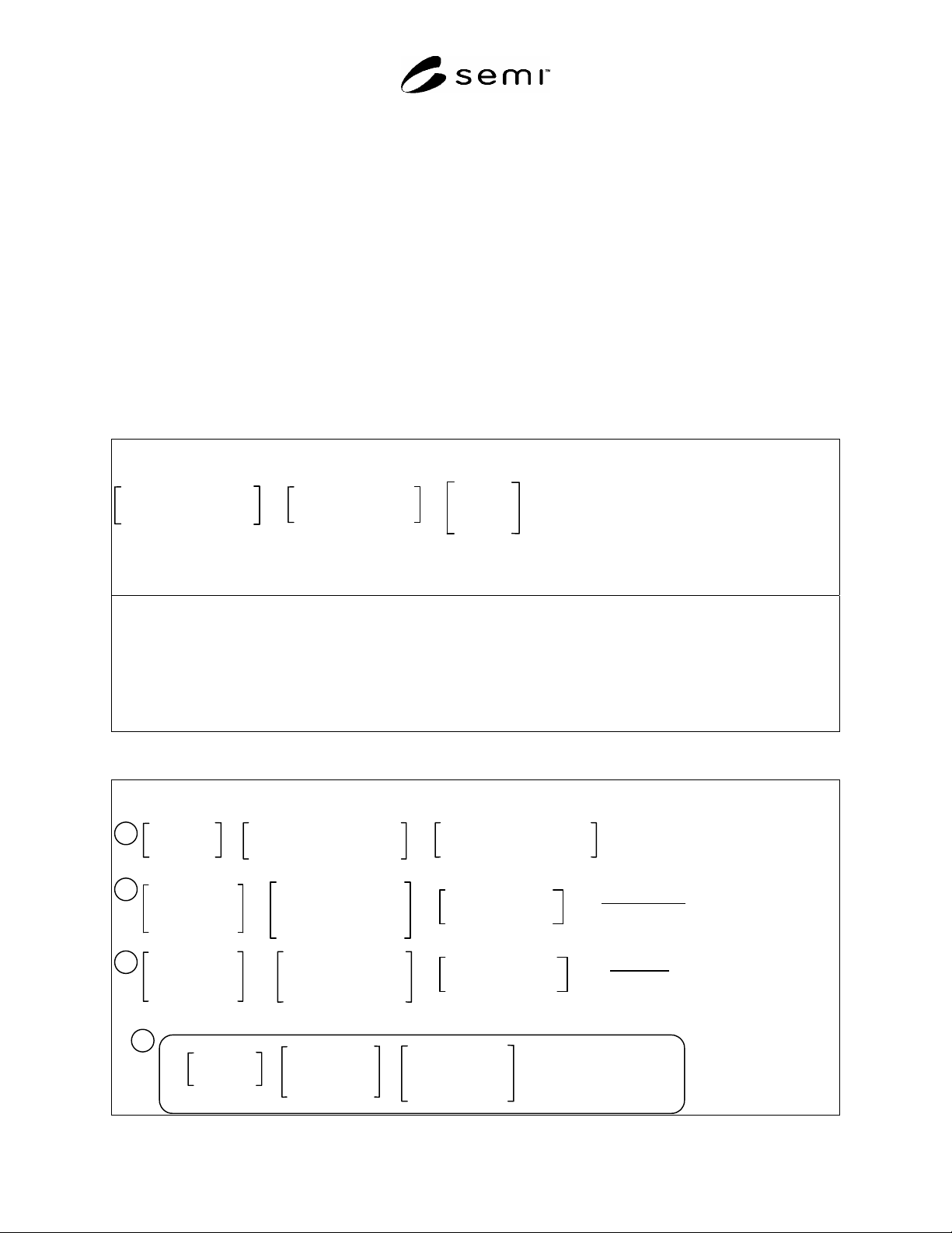
Table R1-2 Energy Conversion Calculation Model and Example
Calculation Model
Use-rate Measurement
(processing or idling)
×
Hours per Year
(processing or idling)
Energy
Conversion
Facto
r
×
=
Estimated Energy
Consumed
per Year
Estimated Hours per Year: Processing = 6132; Idling = 2190
Example Calculation (processing)
Cooling Water (20-25C) for recipe “X”
Use rate measured during processing: 0.500 gal/min = 0.114 m
3
/hr
Annual amount used for processing: 0.114 m
3
/hr x 6,132 hr = 698 m
3
Estimated annual energy equivalent: 698 m
3
x 1.78 kWh/m
3
= 124x10
1
kWh
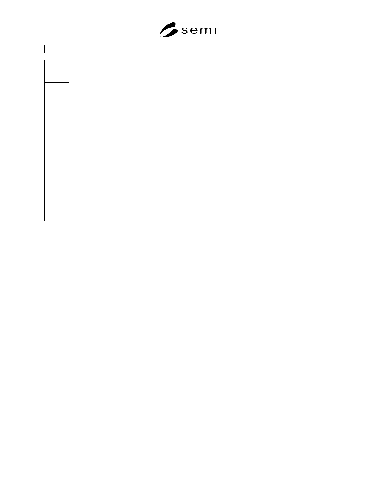
Table R1-3 Heat Load Calculation Model and Example
Calculation Model
Heat Removal
per Year
ai
r
Volume of air
exhausted from
equipment per year
Heat Removal
per Year
water
Volume of water
exhausted from
equipment per year
Heat Removal
per Year
air
Heat Removal
per Year
water
Heat Input
per Year
–
+
–
=
Estimated Heat
Burden per Year
Heat Input
per Year
=
E
lectrical energy input to
equipment per year
Other Heat Sources
(e.g. chemical reactions)
×
=
(Inlet air temp) –
(Outlet air temp)
×
3.24x10
-4
kWh
m
3
°C
×
=
(Inlet water temp) –
(Outlet water temp)
×
1.16 kWh
m
3
°C
1
2
3
4
Removal via Air Conv. Factor
Removal via Water Conv. Factor
SEMI S23-0705 © SEMI 2005 13
Example Calculation (idling) for Recipe “X”
Electricity
Mean real power = 4.16E + 1 kW
Heat Input per Year = 4.16E + 1 kW × 2190 hr = 9.11E + 4 kWh (no other heat input sources)
Air Exhaust
Specified source temperature = 18°C Measured average output temperature = 23°C
Mean temperature difference = 5°C Measured exhaust rate = 50 cfm (5.1E + 3 m
3
/hr)
Volume used per year = 5.1E + 3 m
3
/hr × 2190 hr = 1.12E + 7 m
3
Heat Removal per year = (5°C × 1.12E + 7 m
3
× 3.24E 4 kWh/(m
3
°C) = 1.81E + 4 kWh
Cooling Water
Specified ambient temperature = 20°C Measured average output temperature = 22°C
Mean temperature difference = 2°C Measured flow rate = 1 L/m (0.06 m
3
/hr)
Volume used per year = 0.06 m
3
/hr × 2190 hr = 1E + 2 m
3
Heat Removal per year = (2°C × 1E + 2 m
3
× 1.16 kWh/(m
3
°C) = 2E + 2 kWh
Room Heat Burden
9.11E + 4 kWh – 1.81E + 4 kWh – 2E + 2 kWh = 7.28E + 4 kWh
NOTICE: SEMI makes no warranties or representations as to the suitability of the standards set forth herein for any
particular application. The determination of the suitability of the standard is solely the responsibility of the user.
Users are cautioned to refer to manufacturer's instructions, product labels, product data sheets, and other relevant
literature, respecting any materials or equipment mentioned herein. These standards are subject to change without
notice.
By publication of this standard, Semiconductor Equipment and Materials International (SEMI) takes no position
respecting the validity of any patent rights or copyrights asserted in connection with any items mentioned in this
standard. Users of this standard are expressly advised that determination of any such patent rights or copyrights, and
the risk of infringement of such rights are entirely their own responsibility.
Copyright by SEMI® (Semiconductor Equipment and Materials
International), 3081 Zanker Road, San Jose, CA 95134. Reproduction of
the contents in whole or in part is forbidden without express written
consent of SEMI.

SEMI S24-0705 © SEMI 2005 1
SEMI S24-0705
SAFETY GUIDELINE FOR MULTI-EMPLOYER WORK AREAS
This specification was technically approved by the global Environmental Health and Safety Committee. This
edition was approved for publication by the global Audits and Reviews Subcommittee on May 20, 2005. It
was available at www.semi.org in June 2005 and on CD-ROM in July 2005.
1 Purpose
1.1 This safety guideline provides methods to establish safe working environment where personnel of different
companies (entities) share a work area in a fab or where work by employees of one company in one area may
comprise a hazard to employees of another company in an adjacent area.
2 Scope
2.1 Applicability
2.1.1 This Safety Guideline applies to work areas shared by personnel of different companies, such as equipment
suppliers, facility suppliers, user’s contractors and users.
2.1.2 This Safety Guideline applies where work by employees of one company in one work area comprises a hazard
to employees of another company in an adjacent work area.
2.1.3 The work activities to which this safety guideline applies include installation, start-up, de-installation, wafer
size conversion, and overhaul.
2.2 Criteria Established
2.2.1 This guideline establishes criteria for the user’s, supplier’s and contractor’s responsibility for a safe working
environment.
2.2.2 This guideline establishes criteria for the responsibilities of each supplier’s and contractor’s work supervisors.
2.2.3 This guideline establishes criteria for a Safety Supervisors' Communication Council (SSCC) as the
organization to ensure human safety in multi-employer work areas and where work by employees of one company in
one work area comprises a hazard to employee of another company in an adjacent work area.
2.2.4 This guideline establishes criteria for methods of safety patrol with the user's support in multi-employer work
areas and where work by employees of one company in one work area comprises a hazard to employees of another
company in an adjacent work area.
2.2.5 This guideline contains the following sections:
Purpose
Scope
Limitation
Referenced Standards
Terminology
General Concept
User Actions
Work Supervisor
Safety Supervisors’ Communication Council (SSCC)
Safety Patrol
NOTE 1: An example of observation check sheet for the safety patrol is given in the RI 1.