semi合集-English.pdf - 第7283页
SEMI MF847-0705 © SEMI 2003, 2005 3 6 Hazards 6.1 These test m ethods use X radiation; it is absolutely necessary to av oid personal exposure to X rays. 6.1.1 It is especially im portant to keep hands or finge rs out of …

SEMI MF847-0705 © SEMI 2003, 2005 2
2.5 The values stated in SI units are to be regarded as the standard. The inch-pound values given in parentheses are
for information only.
NOTICE: This standard does not purport to address safety issues, if any, associated with its use. It is the
responsibility of the user of this standard to establish appropriate safety and health guides and determine the
applicability of regulatory or other limitations prior to use.
3 Limitations
3.1 The alignment of the flat against the reference fence may be affected by the straightness of the flat. In the
unlikely event that the flat profile is convex, the flat orientation may not be unique. More often the flat surface will
touch the reference fence along two lines perpendicular to the wafer surface at two points. In this case, the
orientation determined is that of the plane through the two lines on the plane perpendicular to the wafer surface that
passes through the two points. In the latter cases, the orientation determined is that which is obtained in subsequent
processing of the wafer when the alignment is between the flat and a reference fence.
3.2 Misalignment of the various fixtures degrades both the interlaboratory reproducibility and the absolute accuracy
of both test methods. The single-instrument repeatability is not degraded provided the fixturing is rigid.
4 Referenced Standards and Documents
4.1 SEMI Standards
SEMI M1 — Specifications for Polished Monocrystalline Silicon Wafers
SEMI M59 — Terminology for Silicon Technology
SEMI MF26 — Test Methods for Determining the Orientation of a Semiconductive Single Crystal
4.2 ASTM Standards
E 82 — Test Method for Determining the Orientation of a Metal Crystal
3
E 122 — Practice for Choice of Sample Size to Estimate a Measure of Quality for a Lot or Process
4
4.3 DIN Standard
50433, Part 3 — Determination of the Orientation of Single Crystals by Means of Laue Back Scattering
5
4.4 ANSI Standard
ANSI/ASQC Z1.4 — Sampling Procedures and Tables for Inspection by Attributes
6
4.5 Other Standard
Code of Federal Regulations, Title 10, Part 20, Standards for Protection Against Radiation
7
NOTICE: Unless otherwise indicated, all documents cited shall be the latest published versions.
5 Terminology
5.1 Definitions
5.1.1 Terms relating to silicon technology are defined in SEMI M59.
3 Annual Book of ASTM Standards, Vol 03.01, ASTM International, 100 Barr Harbor Drive, West Conshohocken, PA 19428. Telephone: 610-
832-9500, Fax: 610-832-9555, Website:
www.astm.org.
4 Annual Book of ASTM Standards, Vol 14.02.
5 Deutches Institut für Normung standards are available in both English and German editions from Beuth Verlag GmbH, Burggrafenstrasse 6,
10787 Berlin, Germany, Telephone: 49.30.2601-0, Fax: 49.30.2601.1263, Website:
www.beuth.de.
6 American National Standards Institute, American National Standards Institute, New York Office: 25 West 43rd Street, New York, NY 10036,
USA. Telephone: 212.642.4900, Fax: 212.398.0023, Website:
www.ansi.org
.
7 Published in Federal Register, Nov. 16, 1960. Available from Superintendent of Documents, U.S. Government Printing Office, Washington,
DC 20402.

SEMI MF847-0705 © SEMI 2003, 2005 3
6 Hazards
6.1 These test methods use X radiation; it is absolutely necessary to avoid personal exposure to X rays.
6.1.1 It is especially important to keep hands or fingers out of the path of the X rays and to protect the eyes from
scattered secondary radiation.
6.1.2 The use of commercial film badge or dosimeter service is recommended, together with periodic checks of the
radiation level at the hand and body positions with a Geiger-Muller counter calibrated with a standard nuclear
source.
NOTE 2: The present maximum permissible dose for total body exposure of an individual to external X-radiation of quantum
energy less than 3 MeV over an indefinite period is 1.25 R (3.22 × 10
4
C/kg) per calendar quarter (equivalent to 0.6 mR/h
(1.5 × 10
7
C/kg·h)) as established in the Code of Federal Regulations, Title 10, Part 20. The present maximum permissible dose
of hand and forearm exposure under the same conditions is 18.75 R (4.85 × 10
3
C/kg) per calendar quarter (equivalent to 9.3
mR/h (2.4 × 10
6
C/kg·h)). Besides the above stated regulations, various other government and regulatory organizations have
their own safety requirements.
6.1.3 It is the responsibility of the user to make sure that the equipment and the conditions under which it is used
meet applicable regulations.
7 Sampling
7.1 Unless otherwise specified, ASTM Practice E 122 shall be used.
7.2 When so specified, appropriate sample sizes shall be selected from each lot according to ANSI/ASQC Z1.4.
7.3 Inspection levels shall be agreed upon between the parties to the test.
TEST METHOD A — X-RAY EDGE DIFFRACTION METHOD
8 Summary of Test Method
8.1 In this test method a holding fixture that uniquely orients the wafer being tested with respect to its geometric
features is used to position the wafers with respect to the X-ray goniometer.
8.2 The goniometer is rotated to determine the Bragg angle with respect to the geometric features by X-ray
diffraction from the crystallographic planes of the wafer edge, first with the wafer front surface up and then with
front surface down.
8.3 The average angular deviation is calculated from the goniometer readings.
9 Apparatus
9.1 X-ray and Goniometer Apparatus — In accordance with ¶5.1 of SEMI MF26, except that the X-ray beam shall
be collimated using a vertical slit.
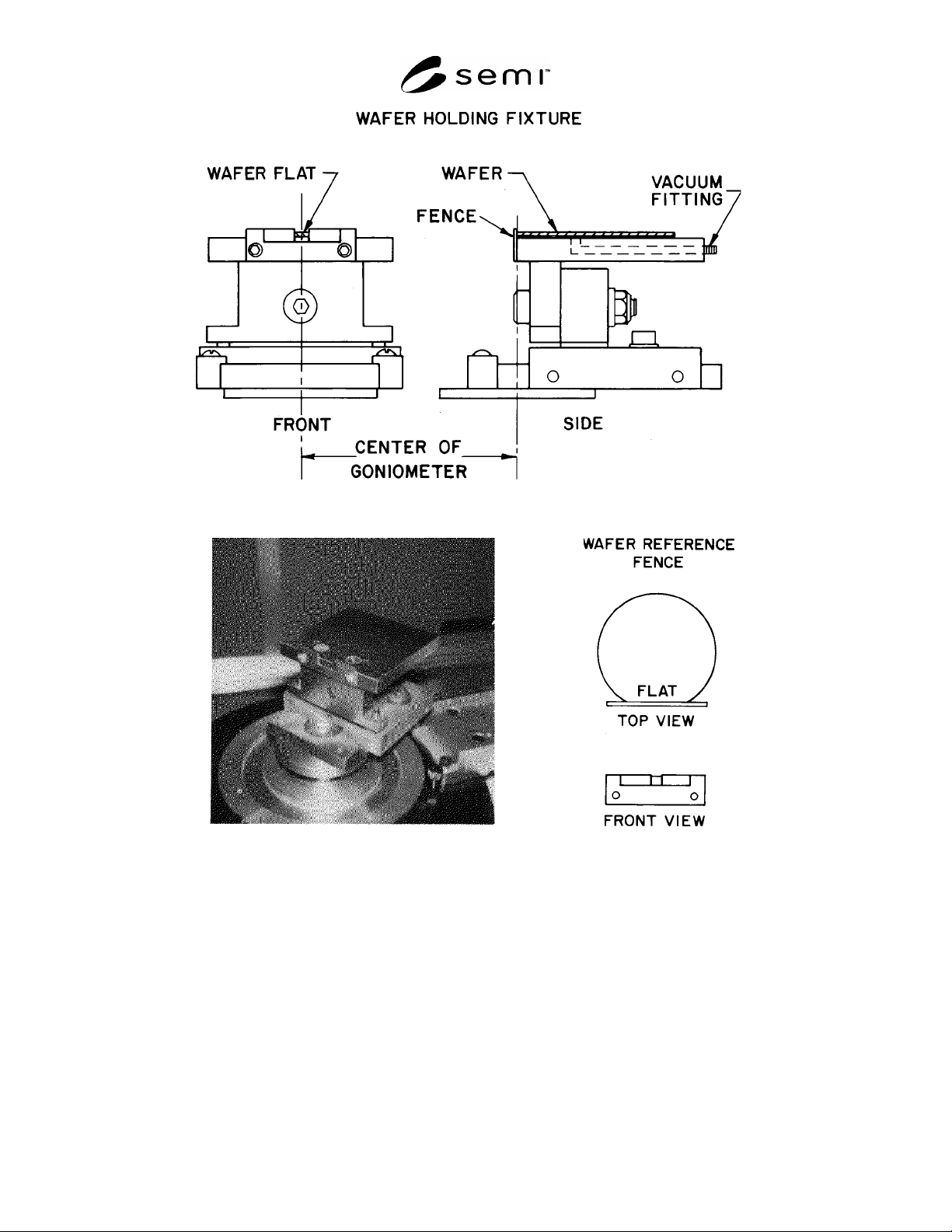
9.2 Wafer-Holding Fixture, to orient the sample wafer uniquely with respect to the X-ray goniometer (see Figure 1).
The fixture must include a vacuum hold-down with a flat horizontal surface and a reference fence perpendicular to
this surface. These components establish an x-y axis that is fixed with respect to the goniometer and the X-ray
beam. The exact dimensions of the fixture depend on the layout of the X-ray apparatus. The critical features are:
SEMI MF847-0705 © SEMI 2003, 2005 4
a. Front and Side Views
b. Photograph of Mounted Fixture c. Detail of Wafer and Reference Fence
Figure 1
Wafer Holding Fixture for X-Ray Edge Diffraction Method
9.2.1 The horizontal surface must be parallel to the plane of the X-ray beam so that the diffracted beam impinges on
the detector (see Figure 2).
9.2.2 Both the side of the reference fence against which the wafer flat is located, and the fixture surface to which
the reference fence mates, must be flat to within one part in 10,000.