semi合集-English.pdf - 第764页
SEMI E103-0704 © SEMI 2000, 2004 4 RELATED INFORMATION 1 APPLICATION NOTES NOTICE : This relat ed information is not an offici al part of SEMI E 103 but was approved for pu blication by f ull letter ballot procedures on …
SEMI E103-0704 © SEMI 2000, 2004 3
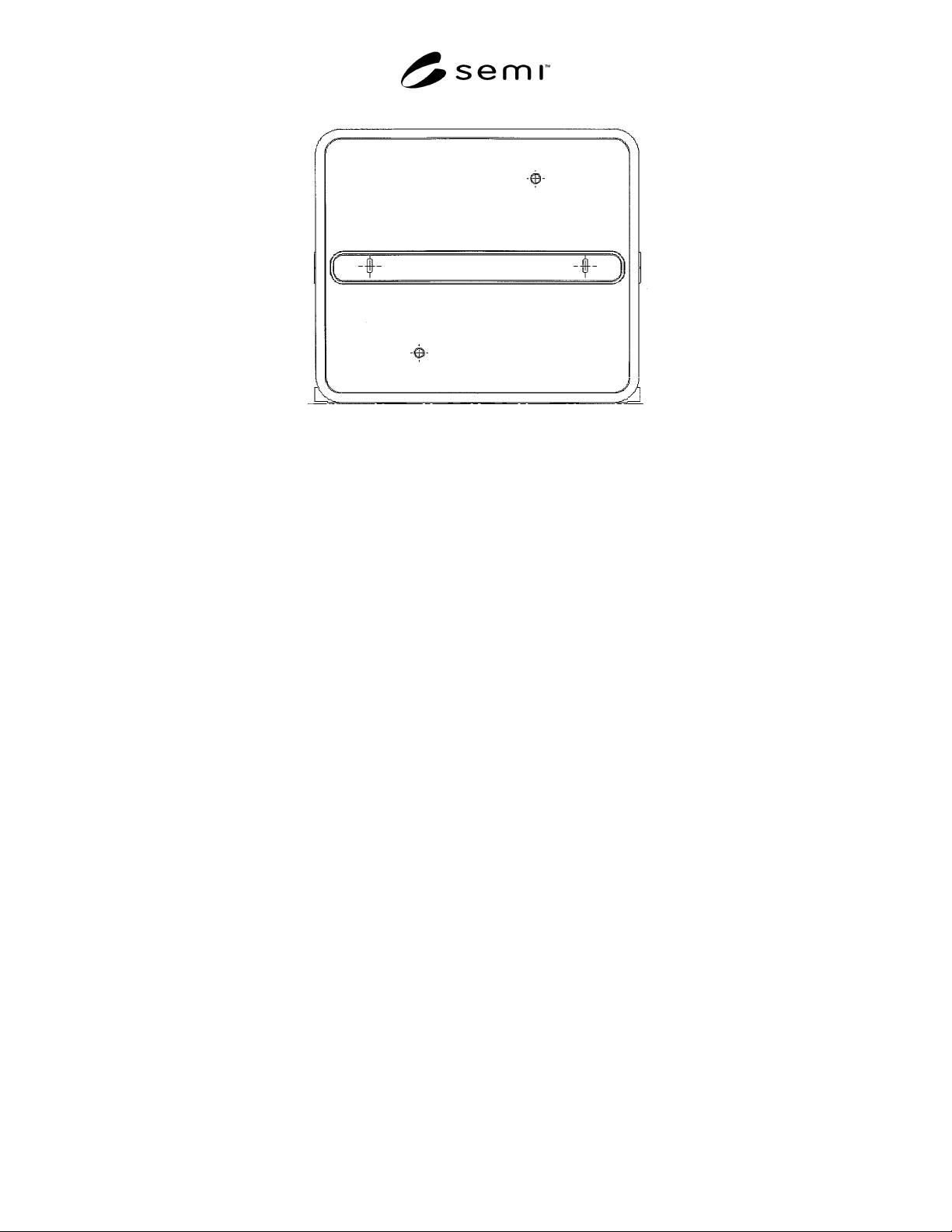
Figure 2
Front View of Example Single-Wafer Box and SWIF
6.7 SWIF Sensing — It is possible that the SWIF is not
removed from the load port when single-wafer boxes
are removed and replaced on the SWIF. However,
when the single-wafer box is removed from the SWIF,
all of the carrier sensing pads (defined in Section 6.6 of
SEMI E1.9) on the bottom of the SWIF must be raised
(so that the load port can sense a change of carriers by
its carrier placement sensor, if any). However, in order
to ensure that the SWIF triggers most optical carrier
presence detectors on the load port, the SWIF (without
a single-wafer box) must block any line of sight
through a volume consisting of the smallest cylindrical
section that contains all of the wafer pick-up volumes
(defined in SEMI E1.9) of the corresponding FOUP
(defined in SEMI E47.1). Note that this standard does
not prevent the use of other kinds of carrier presence
detectors (such as sensors that detect weight on the load
port).
7 Related Documents
7.1 SEMI Standards
SEMI E15.1 — Specification for 300 mm Tool Load
Port
SEMI E57 — Mechanical Specification for Kinematic
Couplings Used to Align and Support 300 mm Wafer
Carriers
SEMI E63 — Mechanical Specification for 300 mm
Box Opener/Loader to Tool Standard (BOLTS-M)
Interface
SEMI E72 — Specification and Guide for 300 mm
Equipment Footprint, Height, and Weight
SEMI E92 — Specification for 300 mm Light Weight
and Compact Box Opener/Loader and Tool-Interface
Standard (BOLTS-Light)
SEMI M31 — Provisional Mechanical Specification for
Front-Opening Shipping Box Used to Transport and
Ship 300 mm Wafers
SEMI S8 — Safety Guidelines for Ergonomics/ Human
Factors Engineering of Semiconductor Manufacturing
Equipment
NOTICE: Unless otherwise indicated, all documents
cited shall be the latest published versions.
NOTICE: SEMI makes no warranties or representa-
tions as to the suitability of the specification set forth
herein for any particular application. The determination
of the suitability of the specification is solely the
responsibility of the user. Users are cautioned to refer
to manufacturer’s instructions, product labels, product
data sheets, and other relevant literature respecting any
materials mentioned herein. These specifications are
subject to change without notice.
The user’s attention is called to the possibility that
compliance with this specification may require use of
copyrighted material or of an invention covered by
patent rights. By publication of this specification,
SEMI takes no position respecting the validity of any
patent rights or copyrights asserted in connection with
any item mentioned in this specification. Users of this
specification are expressly advised that determination
of any such patent rights or copyrights, and the risk of
infringement of such rights, are entirely their own
responsibility.

SEMI E103-0704 © SEMI 2000, 2004 4
RELATED INFORMATION 1
APPLICATION NOTES
NOTICE: This related information is not an official part of SEMI E103 but was approved for publication by full
letter ballot procedures on July 28, 2000.
R1-1
R1-1.1 In fabs in which this system (of single-wafer box and SWIF) is used, equipment should have control
software algorithms that prevent end effectors and wafer slot mappers from entering the carrier except in the
clearances around the middle wafer (defined in Section 6.2) when the presence of this system is detected. A variety
of methods for differentiating the system from ordinary FOUPs are possible.
R1-1.2 Using sensors, equipment can differentiate the system (of single-wafer box and SWIF) from ordinary
FOUPs. For example, sensors below the info pad B location on the load port and on the FIMS door (opposite the
seal zones or the reserved spaces for vacuum application on the box door) could indicate that the carrier type is an
open cassette but with a FOUP door, together implying the presence of this system (of a single-wafer box and
SWIF). Note that such sensors on the load port are not currently specified in any SEMI standard.
R1-1.3 Carrier ID tags can inform the equipment that the load port holds this system (of single-wafer box and
SWIF) instead of an ordinary FOUP.
R1-1.4 Messages from the host computer system can inform the equipment that the load port holds this system (of
single-wafer box and SWIF) instead of an ordinary FOUP.
NOTICE: SEMI makes no warranties or representations as to the suitability of the specification set forth herein for
any particular application. The determination of the suitability of the specification is solely the responsibility of the
user. Users are cautioned to refer to manufacturer’s instructions, product labels, product data sheets, and other
relevant literature respecting any materials mentioned herein. These specifications are subject to change without
notice.
The user’s attention is called to the possibility that compliance with this specification may require use of
copyrighted material or of an invention covered by patent rights. By publication of this specification, SEMI takes
no position respecting the validity of any patent rights or copyrights asserted in connection with any item mentioned
in this specification. Users of this specification are expressly advised that determination of any such patent rights or
copyrights, and the risk of infringement of such rights, are entirely their own responsibility.
Copyright by SEMI® (Semiconductor Equipment and Materials
International), 3081 Zanker Road, San Jose, CA 95134. Reproduction o
f
the contents in whole or in part is forbidden without express written
consent of SEMI.

SEMI E104-0303 © SEMI 2000, 2003 1
SEMI E104-0303
SPECIFICATION FOR INTEGRATION AND GUIDELINE FOR
CALIBRATION OF LOW-PRESSURE PARTICLE MONITOR
This specification was technically approved by the Global Metrics Committee and is the direct responsibility
of the European Equipment Automation Committee. Current edition approved by the European Regional
Standards Committee on January 8, 2003. Initially available at www.semi.org January 2003; to be published
March 2003. Originally published October 2000; previously published March 2002.
1 Purpose
1.1 The use of in situ particle monitoring (ISPM;
particle measurements performed while the wafer
resides inside the processing chamber) in low-pressure
and vacuum applications provides a number of
advantages for defect, process, and equipment
management such as:
• Reduction of particle test wafers used for off-line
tests and saving operator time,
• Optimization and real-time characterization of the
process,
• Advanced process control,
• Advanced equipment control,
• Monitoring process chamber conditions, and
• Optimization of cleaning procedures and
maintenance.
1.1.1 Therefore, ISPM achieves more equipment
availability and faster ramp-up of the production,
reduces cost of ownership, improves quality and yield.
To reach these goals, ISPM needs to be easily
integrated into new or existing process equipment and
the acquisition as well as the analysis of the particle
data needs to be automated. The ISPM sensor should
not have any negative influence on the process and the
measurement has to represent the main particle flow.
The sensor should be designed to have a minimum
negative impact on the parameters defined in SEMI E10
for the whole semiconductor process equipment, to
achieve an advantage in capacity.
1.2 This standard is intended to stipulate operating
conditions, mechanical, electrical, and communication
interfaces for the use of Low-pressure Particle
Detectors integrated in semiconductor process
equipment. A guideline for a reference calibration of
those sensors is intended to support correlation between
measurements with different sensors.
2 Scope
2.1 This standard applies to particle measurement
under low-pressure and vacuum conditions in
semiconductor manufacturing equipment.
NOTICE: This standard does not purport to address
safety issues, if any, associated with its use. It is the
responsibility of the users of this standard to establish
appropriate safety health practices and determine the
applicability of regulatory or other limitations prior to
use.
3 Referenced Standards
3.1 SEMI Standards
SEMI C6.5 — Particle Specification for Grade 10/0.2
Nitrogen (N
2
) and Argon (Ar) Delivered as Pipeline
Gas
SEMI C6.6 — Particle Specification for Grade 10/0.1
Nitrogen (N
2
) and Argon (Ar) Delivered as Pipeline
Gas
SEMI E4 — SEMI Equipment Communications
Standard 1 Message Transfer (SECS-I)
SEMI E5 — SEMI Equipment Communications
Standard 2 Message Content (SECS-II)
SEMI E10 — Specification for Definition and
Measurement of Equipment Reliability, Availability,
and Maintainability (RAM)
SEMI E33 — Specification for Semiconductor
Manufacturing Facility Electromagnetic Compatibility
SEMI E37 — High-Speed SECS Message Services
(HSMS) Generic Services
SEMI E54 — Sensor/Actuator Network Standard
SEMI E54.10 — Specification for Sensor/Actuator
Network Specific Device Model for an In-Situ Particle
Monitor Device
SEMI F6 — Guide for Secondary Containment of
Hazardous Gas Piping Systems