semi合集-English.pdf - 第7695页
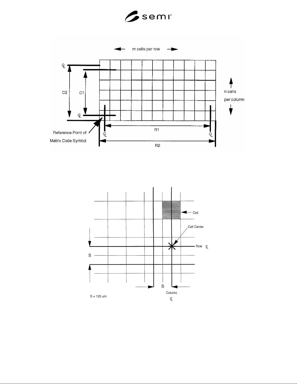
SEMI T8-0698 E © SEMI 1998, 2004 4 Figure 1 Data Matrix Field Figure 2 Data Matrix Cell Dimensions
SEMI T8-0698
E
© SEMI 1998, 2004 3
6.2 Content of the Data Matrix Code Symbol
6.2.1 Each rectangular matrix code symbol shall
contain between 15 and 46 message characters, together
with the error checking and correcting (ECC) 200 code
characters, encoded in accordance with AIM
International Symbology Specification - Data Marix.
6.2.2 The message characters may include any of those
designated as “mostly upper case” in Table 5 and
Annex K of AIM International Symbology
Specification - Data Marix. 8-bit characters may also be
encoded with reduced field capacity (see Table 3). The
first 15 message characters shall contain two elements:
a. a vendor-assigned 8-character substrate
identification code, followed by
b. a 7-character vendor identification code as defined
by UCC. These are a six-digit company
identification, preceded by a zero (0).
6.2.2.1 The remaining message characters, if any, shall
contain information as agreed between the vendor and
user. This may require field identifiers and field
concatenators (see ANSI MH10.8.2).
6.3 Location of the Data Matrix Code Symbol
6.3.1 With the substrate positioned front surface up and
with the orientation corner toward the operator and to
the operator's left, the reference point of the data matrix
code symbol shall be placed toward the orientation
corner as specified in Table 3.
The 12 row × 26 column rectangular 2-D matrix
code symbol shall be placed entirely outside the fixed
quality area (FQA) and within a nominal edge
exclusion area of 10 mm. Large symbols will extend
toward the substrate center and perpendicular to the
substrate edges. (See Table 1 for field dimensions.)
6.3.3 The primary row of the symbol shall be parallel
to the adjacent edge of the substrate ± 10.0°. The
primary column of the symbol shall be nominally
perpendicular to the same edge. The symbol shall lie
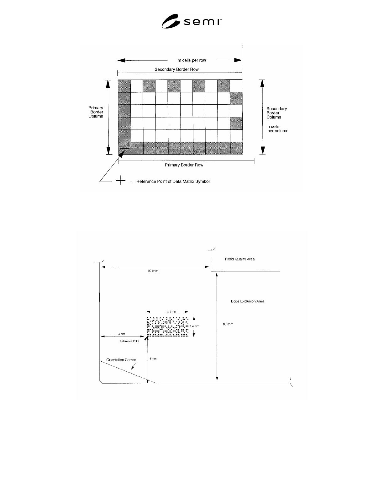
between these two edges and the FQA (see Figures 4
and 5). The reference point of the symbol shall be
located 4.0 ± 1.0 mm from the adjacent edge of the
substrate.
Table 1 2-D Data Matrix Code Symbol Dimensions
Rectangular Array Spacing
# of Cells
in Row
# of Cells
in Column
C
1
(mm)
R
1
(mm)
C
2
(mm)
R
2
(mm)
12 26 1.375 3.125 1.500 3.250
12 32 1.375 4.375 1.500 4.500
125 µm
16 36 1.875 4.375 2.000 4.500
Table 2 Message Character Count in Rectangular Arrays for Use on FPD Substrates
# of Cells in Row and Column
12 Rows
26 Columns
12 Rows
36 Columns
16 Rows
36 Columns
Maximum # of Message Characters 8-bit N/A 20 30
Mostly upper-case 22 31 46
Table 3 Location of 2-D Matrix Code Symbol Substrate Back Surface Up, Orientation Corner Toward the
Operator and Toward the Operator’s Left
Type of Array Reference Point Location of Reference Point
Rectangular Common cell of
primary border row and
column
#1
4.0 ± 1.0 mm from the nominal edge of the substrate and toward the
substrate orientation corner.
#1
The rows of the rectangular 2-D matrix code symbol are parallel to the X-edge of a substrate whose orientation corner is in the 1,1,1 orientation
or the 2, -1, 0 orientation.
SEMI T8-0698
E
© SEMI 1998, 2004 4
Figure 1
Data Matrix Field
Figure 2
Data Matrix Cell Dimensions
SEMI T8-0698
E
© SEMI 1998, 2004 5
Figure 3
Border Rows and Columns
Figure 4|
Data Matrix Code Field in Edge Exclusion Area