semi合集-English.pdf - 第7718页
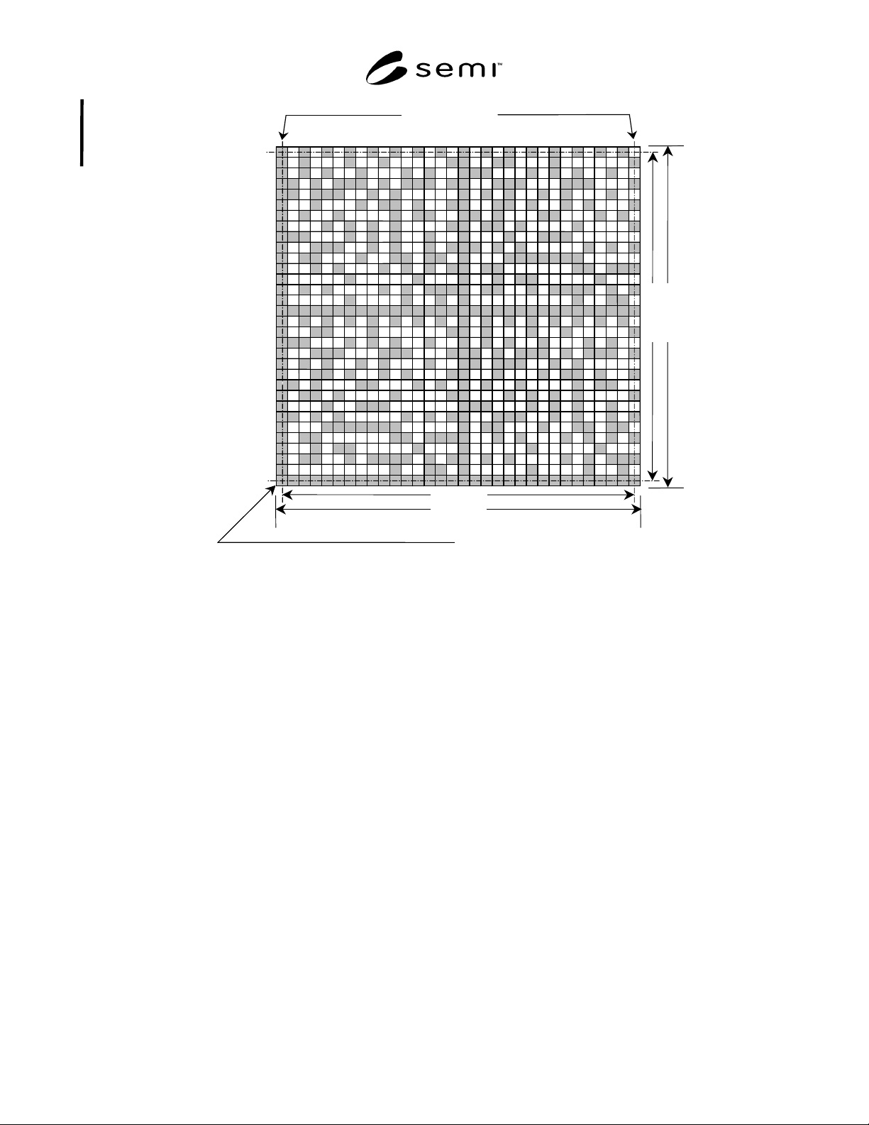
SEMI T11-0703 © SEMI 2002, 2003 3 Data Matrix Cod e Symbol Reference Corner C 2 C 1 R 1 R 2 Secon dary Border Ro w Secon dary Border Column Primar y Border Row Primar y Border Colum n NOTE: All dime nsions in millimet er…
SEMI T11-0703 © SEMI 2002, 2003 2
5.3.3 quiet zone — an unpatterned, unmarked area that
surrounds a mark field.
6 Ordering Information
6.1 Purchase orders for substrates furnished to this
specification shall specify the following optional items:
6.1.1 Number (15 to 91) of message characters.
6.1.2 Content of Message Characters 16 and up, if
present.
7 Requirements
7.1 Data Matrix Code Symbol Dimensions
7.1.1 Each square matrix code symbol shall be
composed of an array of 32 rows and 32 columns (see
Table 1 and Figure 1) as defined in compliance with
ISO/IEC 16022.
7.2 Cell Dimensions
7.2.1 Cell spacing shall be 100 µ m, center to center.
7.2.2 Cell shape shall be square.
7.2.3 Cell size shall be 100 ± 5 µ m.
7.2.4 Dot Misalignment — The symbol shall be
readable in accordance with ISO/IEC 16022.
7.3 Border Rows and Columns (see Figure 1)
7.3.1 One border row and one border column shall
contain a dot in each cell. These are identified as the
primary border row and the primary border column.
These are used by the code reader to determine the
orientation of the matrix.
7.3.1.1 The opposing (secondary) border row and
column shall contain dots in alternating cells, as shown
in Figure 1.
7.3.2 For square Data Matrix code symbols, the
reference point of the symbol is generally the physical
centerpoint of the cell common to the primary border
row and the primary border column. However, for the
present application it is more convenient to reference
the location of the Data Matrix code symbol to the
bottom left corner of the cell containing the reference
point, identified in the figures as the “reference corner.”
7.4 Quiet Zone
7.4.1 The quiet zone surrounding the Data Matrix code
symbol shall be four cells (400 µm) wide.
7.4.2 The area between the quiet zone and the nearest
side of the pellicle frame shall be filled with an
unpatterned chrome film.
7.5 Content of the Data Matrix Code Symbol
7.5.1 Each square Data Matrix code symbol shall
contain between 15 and 91 message characters, together
with error checking and correcting (ECC) 200 code
characters, encoded in accordance with ISO/IEC 16022.
7.5.2 The message characters may include any of those
designated as EDIFACT in Table 5 and Annexe J.3 of
ISO/IEC 16022.
7.5.3 The first 15 message characters shall contain
supplier-assigned 8-character substrate identification
code, followed by a 7-character supplier (manufacturer)
identification code defined by UCC as a six-digit
company identification, preceded by a zero (0).
7.5.4 The remaining message characters, if any, shall
contain information as agreed between the supplier and
user. This may require field identifiers and field
concatenators (see ANSI MH10.8.2).
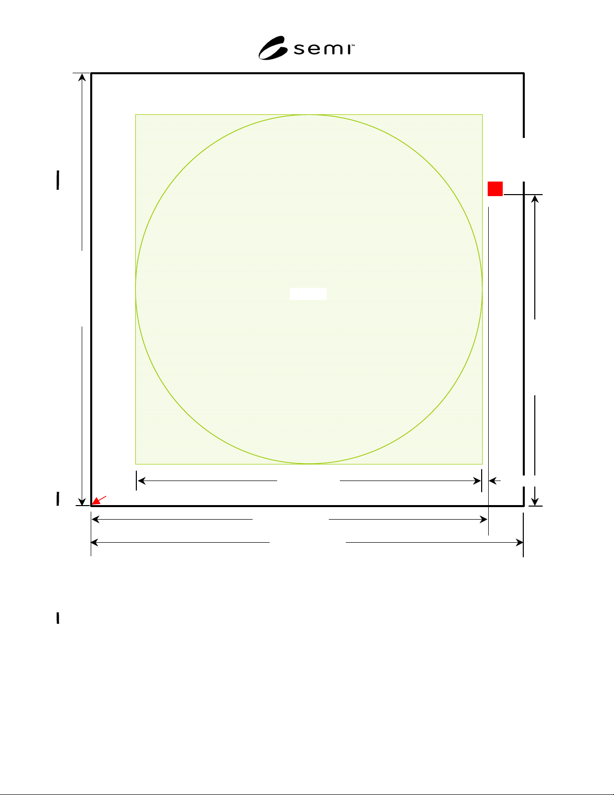
7.6 Location of the Data Matrix Code Symbol
7.6.1 With the substrate positioned front surface up and
with the substrate’s reference corner toward the
operator and to the operator’s left, the lower left corner
of the Data Matrix code symbol shall be located
139.6 ± 0.5 mm to the right and 110.4 ± 0.5 mm above
the substrate’s reference corner.
7.6.2 This places the 32 row × 32 column square Data
Matrix code symbol entirely within a 14 mm wide edge
exclusion area (see Figure 2).
7.6.3 The primary border row of the symbol shall be
parallel with the adjacent edge of the substrate ± 10.0° .
The primary border column of the symbol shall be
nominally perpendicular to the same edge.
7.6.4 Mark Area Dimensions — The mark area shall be
4.0 mm × 4.0 mm.
Table 1 Data Matrix Code Symbol Dimensions
Type of array Square
Cell spacing (center to center)
100 µm (nominal)
Dot size (diameter or edge
length)
100 ± 5 µm
Dot misalignment
10 µm, max.
Number of cells in row 32
Number of cells in column 32
C
1
3.100 mm
R
1
3.100 mm
C
2
3.200 mm
R
2
3.200 mm
Width of quiet zone
400 µm (nominal)
SEMI T11-0703 © SEMI 2002, 2003 3
Data Matrix Code Symbol Reference Corner
C
2
C
1
R
1
R
2
Secondary Border Ro
w
Secondary Border Column
Primary Border Row
Primary Border Column
NOTE: All dimensions in millimeters.
Figure 1
Data Matrix Code Symbol Showing Border Rows and Columns
SEMI T11-0703 © SEMI 2002, 2003 4
139.6
±
0.5
152.0
±
0.4
11
0
.4
±
0
.
5
1
5
2.
0
±
0
.4
124 (nominal)
1.6
±
0.7
Pellicle
Substrate Reference Corner
Data Matrix
Code Symbol
(see detail in
Figure 3)
NOTE: All dimensions in millimeters.
Figure 2
Location of Data Matrix Code Symbol in Reticle Substrate Edge Exclusion Area
(Nominally 14 mm Wide)