semi合集-English.pdf - 第7844页
SEMI T13-1104 © SEMI 2004 4 6.4.1 Service Definition 6.4.1.1 A service definition table de fines the specific set of me ssages for a given service resource, as shown in the following table: Message Service Name Type Desc…

SEMI T13-1104 © SEMI 2004 3
5.2.10 hybrid IC — a kind of Device which has one or more semiconductor dice and other active/passive elements
packaged together.
5.2.11 reusable container — a container for electronics parts which is usually used more than once.
5.2.12 packaged device — a Device which is not exposed in bared shape on substrate for passivation, physical
protection and manipulation purposes. It is often independently packaged by ceramic base or plastic molding with
leads. Sometimes it has more than one dice and some separated electric elements packaged in a package.
5.2.13 strip — rectangular shaped substrate or flexible tape to mount semiconductor devices. The purpose of use is
not only for products but also for carrier or some other purpose used during production of electronics products.
5.2.14 substrate — base on which electronics elements, especially semiconductor devices, are fabricated or on
which electronics parts are mounted. Examples are silicon wafers, flat panel display glass substrates, lead frames,
print circuit boards and so on.
6 Convention
6.1 This section defines the conventions followed by this document.
6.2 Object Conventions — This document conforms to the conventions for objects established by SEMI E39,
including object diagrams, object terminology, and requirements for standardized objects. Accordingly, notation is
based on Unified Modeling Language (UML).
6.2.1 Formal Name of an Object — The text capitalizes formal object name references. Similar to the way
capitalization is normally used when discussing entities. When describing something in the general (like cities)
lower case is used, but when a specific entity is of interest (New York City), then first letters are capitalized.
6.2.2 Components of Complex Attributes — The names of object attributes defined in tables are left-justified. The
individual elements of complex attributes are right-justified in order of appearance below the complex attribute.
6.3 State Model Conventions
6.3.1 This document uses the Harel state chart convention for describing dynamic operation of defined objects. The
outline of this convention is described in an attachment of SEMI E30. The official definition of this convention is
described in “State charts: A Visual Formalism for Complex Systems”
2
.
6.3.2 The Harel convention has not the concept of state models of “creation” and “extinction” for expressing a
temporary entity. The “job” described in this document is such an entity, and a copy of the same state model is used
for an independent job newly created. In this document, a circle with a black circle inside is used for expressing
extinction of an entity. A filled black circle denotes the entry to the state model (the entity creation).
6.3.3 Transition tables are provided in conjunction with the state diagrams to explicitly describe the nature of each
state transition. A transition table contains columns for Transition number, Previous State, Trigger, New State,
Actions, and Comments. The “trigger” (column 3) for the transition occurs while in the “previous” state. The
“actions” (column 5) includes a combination of:
1. Actions taken upon exit of the previous state.
2. Actions taken upon entry of the new state.
3. Actions taken which are most closely associated with the transition.
4. No differentiation is made between these cases.
Num Previous State Trigger New State Actions Comments
6.4 Service Message Representation — Services are functions or methods that may be provided by either the
equipment or the host. A service message may be either a request message, which always requires a response, or a
notification message, that does not require a response.
2 D. Harel, “State charts: A Visual Formalism for Complex Systems”, Science of Computer Programming 8,
1987.
SEMI T13-1104 © SEMI 2004 4
6.4.1 Service Definition
6.4.1.1 A service definition table defines the specific set of messages for a given service resource, as shown in the
following table:
Message Service Name Type Description
6.4.1.2 Type can be either “N” = Notification or “R” = Request & Response.
6.4.1.3 Notification type messages are initiated by the service provider (e.g., the equipment) and the provider does
not expect to get a response from the service user. Request messages are initiated by a service user (e.g., the host).
Request messages ask for data or an activity from the provider. Request messages expect a specific response
message (no presumption on the message content).
6.4.2 Service Parameter Dictionary
6.4.2.1 A service parameter dictionary table defines the description, format and its possible value for parameters
used by services, as shown in the following table:
Parameter Name Description Format: Possible Value
6.4.2.2 A row is provided in the table for each parameter of a service.
6.4.3 Service Message Definition
6.4.3.1 A service message definition table defines the parameters used in a service, as shown in the following table:
Parameter Req/Ind Res/Cnf Comment
6.4.3.2 The columns labeled REQ/IND and RSP/CNF link the parameters to the direction of the message. The
message sent by the initiator is called the “Request”. The receiver terms this message the “Indication” or the request.
The receiver may then send a “Response” which the original sender terms the “Confirmation”.
6.4.3.3 The following codes appear in the REQ/IND and RSP/CNF columns and are used in the definition of the
parameters (eg., how each parameter is used in each direction):
M Mandatory Parameter — Must be given a valid value.
C Conditional Parameter — May be defined in some circumstances and undefined in others. Whether a value is
given may be completely optional or may depend on the value of the other parameter.
U User-Defined Parameter.
- The parameter is not used.
= (For response only.) Indicates that the value of this parameter in the response must match that in the primary (if
defined).
NOTE 1: Concatenated words are often used for names of class, attribute, service and data. However they are official,
sometimes separated words may be preferred in figures and explanatory sentences for readability even they are no differences.
7 General Requirements
7.1 Identification Means — Equipment and other computer or software have to have some means to identify entities
that appear in this document.
7.2 Communication Means — Each entity on equipment and other computer or software has to have some electric
communication means to transact.
SEMI T13-1104 © SEMI 2004 5
8 Overview
8.1 Die Trace Capability — Economic growth around the world makes it possible to get entered into semiconductor
manufacturing business and advanced electronics business which uses semiconductor devices. The number of
semiconductor manufacturing countries and/or companies including subsidiaries and branch divisions is growing.
Procurement by e-commerce makes it easy to purchase semiconductor devices and electronics parts as application of
the devices from emerging companies in wide and distant areas. Suppliers of such devices and parts are required to
have device tracking facilities or die tracing capabilities to reduce security risks, perform quality assurance, improve
quality engineering and some other purpose depending on products.
8.2 Wide Area Communication — Such electronics as cell phones and television sets consist of many
semiconductor devices. They are decomposed into circuit boards, display module, operation panel unit and so on.
Most of such subcomponents also consist of semiconductor devices. They are supplied by semiconductor
manufacturers, set makers or third party suppliers. Tracking semiconductor devices or die tracing does not just
happen in semiconductor manufacturing fab. Close communication with assembly works including print circuit
board (PCB) suppliers and set makers is expected.
8.3 Range of Die Tracing — If traceability expectation were only for confirmation of producer and producing
country, this standard would address backend processes and PCB assembly line. Industries around semiconductor
manufacturing, e.g. automobile and car electronics industries, anticipate more than secure components. To address
that, this document extends the range of specification not only for assembly but also for wafer processes. Some
specific process data including metrology and inspection may be included in target data for die tracing.
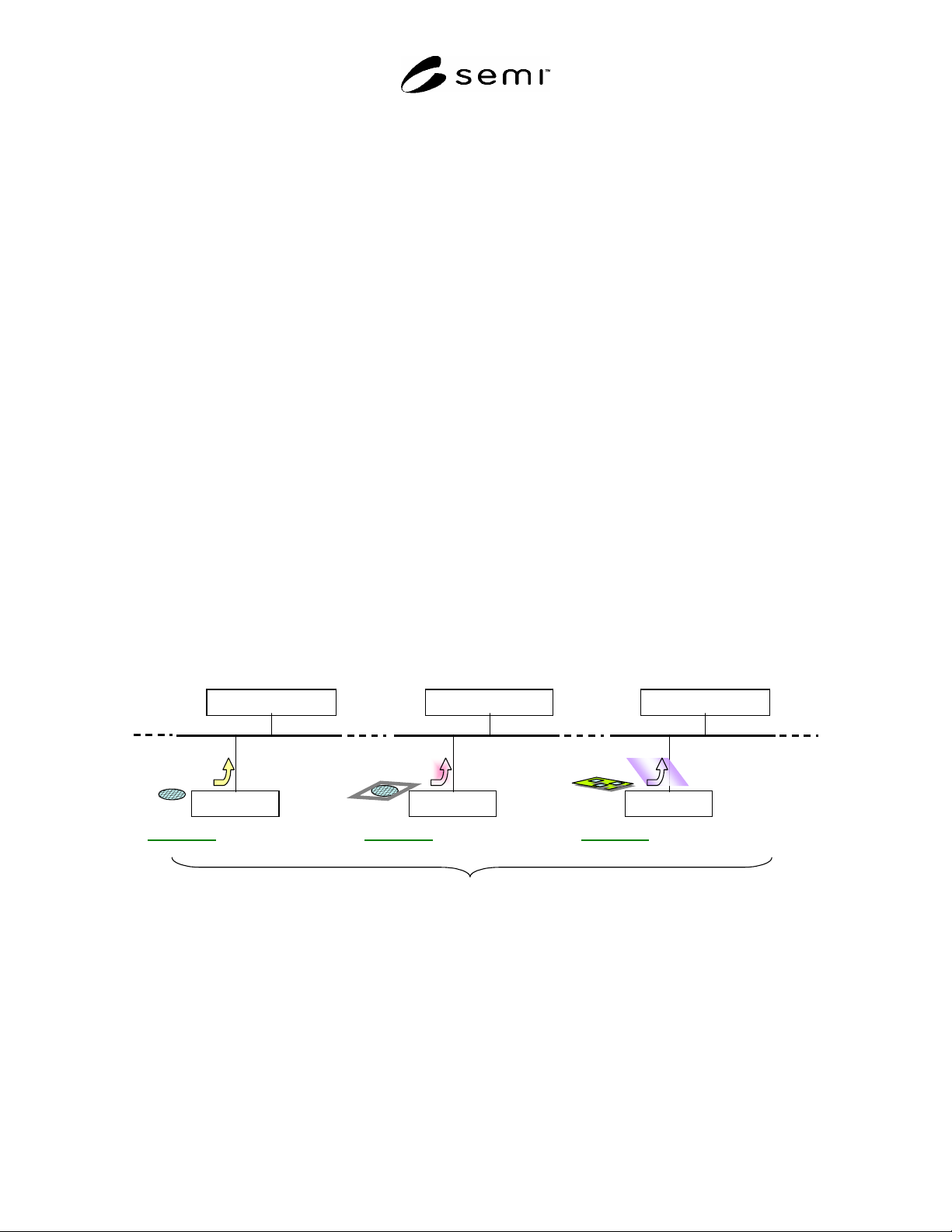
8.4 Die Trace Data — As described above, data traced for a die doesn’t come from just one specific process or a
piece of equipment. Die information is required to be traced on each key equipment. Otherwise it doesn’t make
sense, in other words, tracing system doesn’t work as a whole. Storage for Die Trace Data may or may not be
distributed.
8.5 Variety of Die Trace Data — Tracers collect various kinds of data for die tracing. They may be collation
information of pick & place history from dicing film to lead frame, electric test information for sorting dice or
metrology data on the wafer to which a die belongs. They are just examples of variety of Die Trace Data. Their
generic format can not be specified and unified central tracing system may not be realistic.
dice
Die Trace Data
Trace Data Storage
Equipment-P
Process-A
Material-X
dice
Die Trace Data
Trace Data Storage
Equipment-Q
Process-B
Material-X
dice
Die Trace Data
Trace Data Storage
Equipment-R
Process-C
Material-X
Same Material on Different Equipment types for Different Processes
Figure 1
Example of Die Trace Data on Key Equipment
8.6 Data Source of Die Trace Data — Most Die Trace Data are reported by equipment because die tracing tracks
what happens on a die for process. The things that happen are not for equipment control, process control nor
performance tracking done with execution. But they are for logging to certify the pedigree of a product or to track
back when some serious problem is detected on a product or prevent further damage to application of the product. In
this sense, Die Trace Data may be a part of or summary of MES data, or some calculated data. Equipment may not
be the data source in these cases.
8.7 Data Taxonomy — Die Trace Data can be categorized in various ways: by data source, data type, data form,
semantics and so on. The other classification criteria may be geometric information, deviation of process settings,