semi合集-English.pdf - 第802页
SEMI E110-1102 © SEMI 2001, 2002 4 Y67=25 (Refer to SEMI E47.1.) Bilateral Dat um Plane C L Facial Dat um Plane Switch pla c ement vol ume x404=245 y400=100 x403=75 y401=250 y402=190 Figure 3 Top View of Switch Placement…
SEMI E110-1102 © SEMI 2001, 2002 3
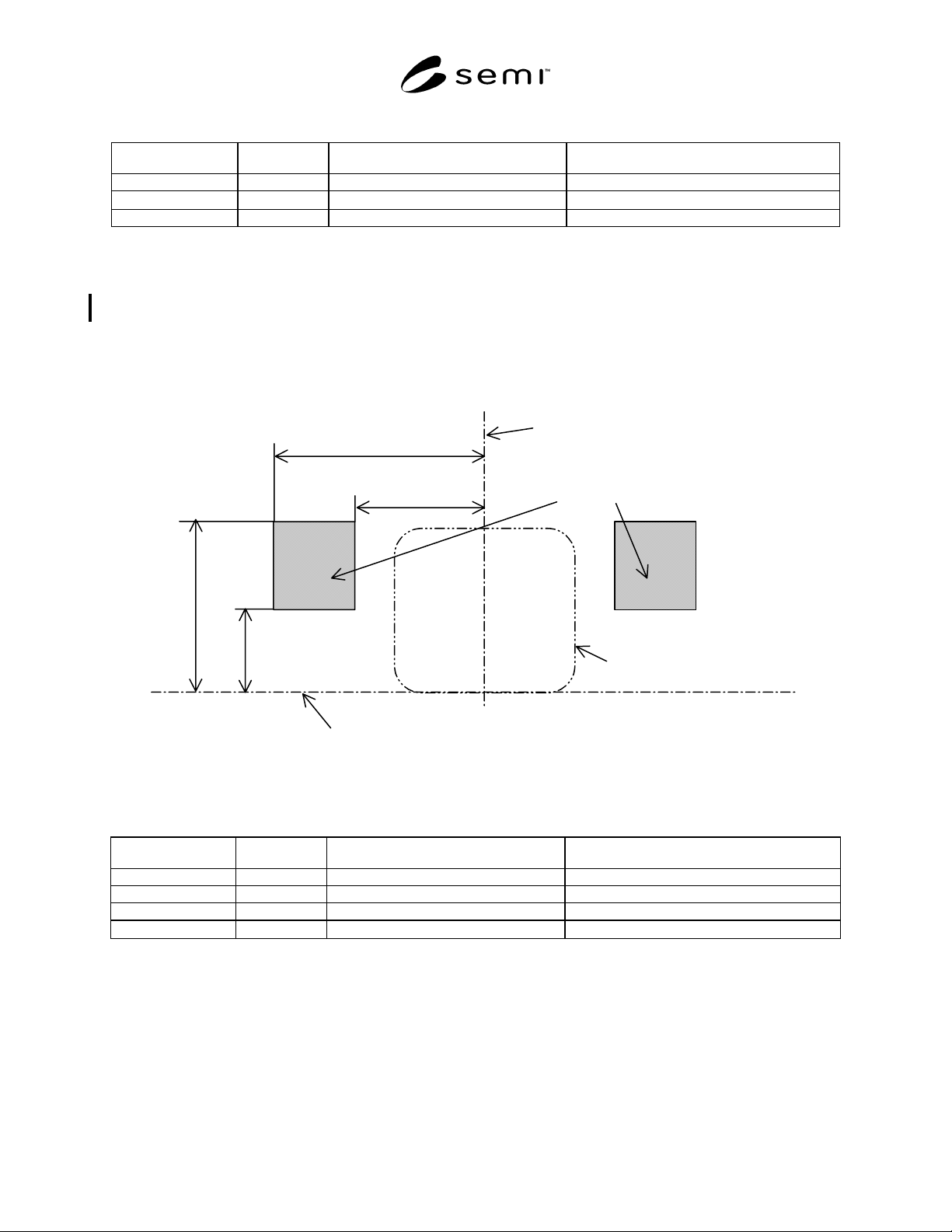
Table 1 Dimensions of indicator placement zone for a load port per SEMI E15.1 Option1
Symbol Used Figure Value Specified Reference Measured From
x400 1 237.5 mm (9.35 in.) bilateral datum plane
z400 1
340 mm (13.39 in.)
horizontal datum plane
z401 1 486 mm (19.13 in.) horizontal datum plane
5.1.2 Indicator placement zone for a load port per SEMI E15.1 Option 3 — It is recommended that load port status
indicators should be positioned within a zone given by x401, x402, z402 and z403. The exact placement of them
within this zone is at the direction of the load port supplier. They may be located at or behind (away from the
operator) the load face plane. Clearances required by SEMI E15.1 cannot be violated.
NOTE 3: The indicator placement zone is not an exclusion zone. No assumption can be made that this zone needs to be kept
empty by the load port supplier. Furthermore, no assumption can be made that a load port must have a physical surface
representing the indicator placement zone.
x402=475
x401=290
z403=390
z402=190
Horizontal Datum Plane
C
L
Bilateral Datum Plane
Indicator placement zone
Approximate FOUP envelope
Figure 2
Indicator Placement Zone for a Load Port Per SEMI E15.1 Option 3
Table 2 Dimensions of indicator placement zone for a load port per SEMI E15.1 Option3
Symbol Used Figure Value Specified Reference Measured From
x401 2 290 mm (11.42 in.) bilateral datum plane
x402 2 475 mm (18.79 in.) bilateral datum plane
z402 2 190 mm (7.48 in.) horizontal datum plane
z403 2
390 mm (15.35 in.)
horizontal datum plane
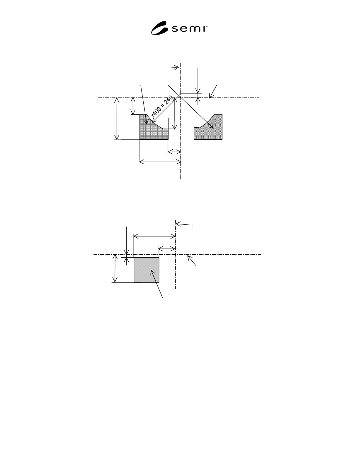
5.2 Switch Placement Volume — For a load port according to option 1 and 3 per SEMI E15.1, it is recommended
that load port operation switches should be positioned in a way, that the surface of the switch is within a volume
given by x403, x404, r400, y402 (equal to the maximum values of r67 and y53
defined in SEMI E47.1 respectively),
y400, y401 (equal to the maximum value of D defined in SEMI E15.1), z404, and z405. The exact placement of the
switches within this volume is at the discretion of the load port supplier.
NOTE 4: The switch placement volume is not an exclusion volume. No assumption can be made that this volume needs to be
kept empty by the load port supplier. Furthermore, no assumption can be made that a load port must have a physical surface
representing the switch placement volume.
SEMI E110-1102 © SEMI 2001, 2002 4
Y67=25
(Refer to
SEMI E47.1.)
Bilateral Datum Plane
C
L
Facial Datum Plane
Switch placement volume
x404=245
y400=100
x403=75
y401=250
y402=190
Figure 3
Top View of Switch Placement Volume
z405=165
Horizontal Datum Plane
C
L
Facial Datum Plane
Switch placement volume
y400=100
z404=15
y401=250
Figure 4
Side View of Switch Placement Volume
SEMI E110-1102 © SEMI 2001, 2002 5
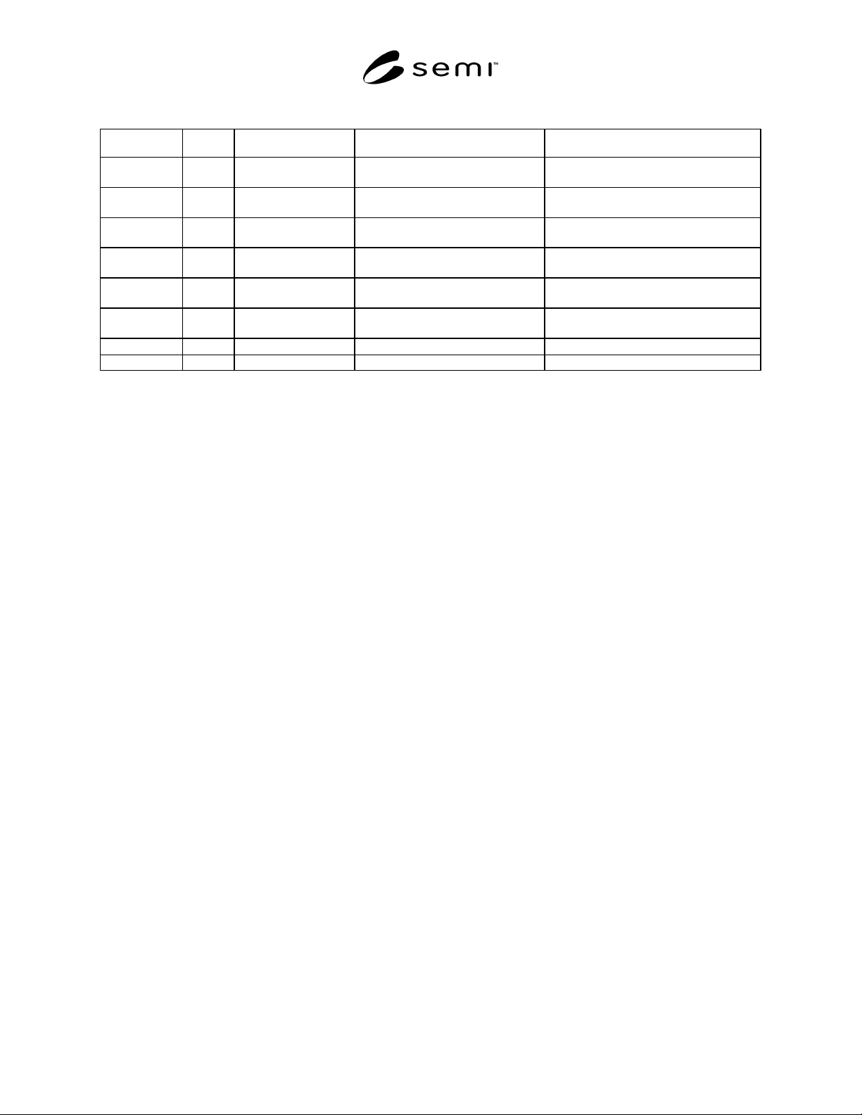
Table 3 Dimensions of Switch Placement Volume
Symbol Used Figure Value Specified Reference Measured From Remarks
r400 3 240 mm (9.45 in)
y67 in front of nominal wafer
center line
Equal to the maximum value of r67
defined in SEMI E47.1
x403 3 75 mm (2.95 in.) bilateral datum plane
-
x404 3 245 mm (9.65 in.) bilateral datum plane
-
y400 3,4 100 mm (3.94 in)
facial datum plane (as shown in
Figure 1 of SEMI E15.1)
-
y401 3,4 250 mm(9.843 in)
facial datum plane (as shown in
Figure 1 of SEMI E15.1)
Equal to the maximum value of D
defined in SEMI E15.1
y402 3 190 mm (7.48 in)
facial datum plane (as shown in
Figure 1 of SEMI E15.1)
Equal to the maximum value of y53
defined in SEMI E47.1
z404 4
15 mm (0.59 in.)
horizontal datum plane
-
z405 4 165 mm (6.50 in.) horizontal datum plane -
6 Related Documents
6.1 SEMI Standards
SEMI E62 — Provisional Specification for 300 mm Front-Opening Interface Mechanical Standard (FIMS)
SEMI E63 — Mechanical Specification for 300 mm Box Opener/Loader to Tool Standard (BOLTS-M) Interface
SEMI E92 — Provisional Specification for 300 mm Light Weight and Compact Box Opener/Loader to Tool-
Interoperability Standard (BOLTS/Light)
SEMI S8 — Safety Guidelines for Ergonomics Engineering of Semiconductor Manufacturing Equipment
NOTICE: SEMI makes no warranties or representations as to the suitability of the standards set forth herein for any
particular application. The determination of the suitability of the standard is solely the responsibility of the user.
Users are cautioned to refer to manufacture' s instructions, product labels, product data sheets, and other relevant
literature, respecting any materials or equipment mentioned herein. These standards are subject to change without
notice.
By publications of this standard, Semiconductor Equipment and Materials International (SEMI) takes no position
respecting the validity of any patent rights or copyrights asserted in connection with any items mentioned in this
standard. Users of this standard are expressly advised that determination of any such patent rights or copyrights, and
the risk of infringement of such rights are entirely their own responsibility.
Copyright by SEMI® (Semiconductor Equipment and Materials
International), 3081 Zanker Road, San Jose, CA 95134. Reproduction o
f
the contents in whole or in part is forbidden without express written
consent of SEMI.