semi合集-English.pdf - 第853页
SEMI E114-0302 E © SEMI 2002 7 Short Circuit Termina tion Cable As sembly t o be tested Test P ort TDR NOTE: The cable ass embly to be test ed (DUT) attaches to the test port and is term inated with a short circuit. Figu…
SEMI E114-0302
E
© SEMI 2002 6
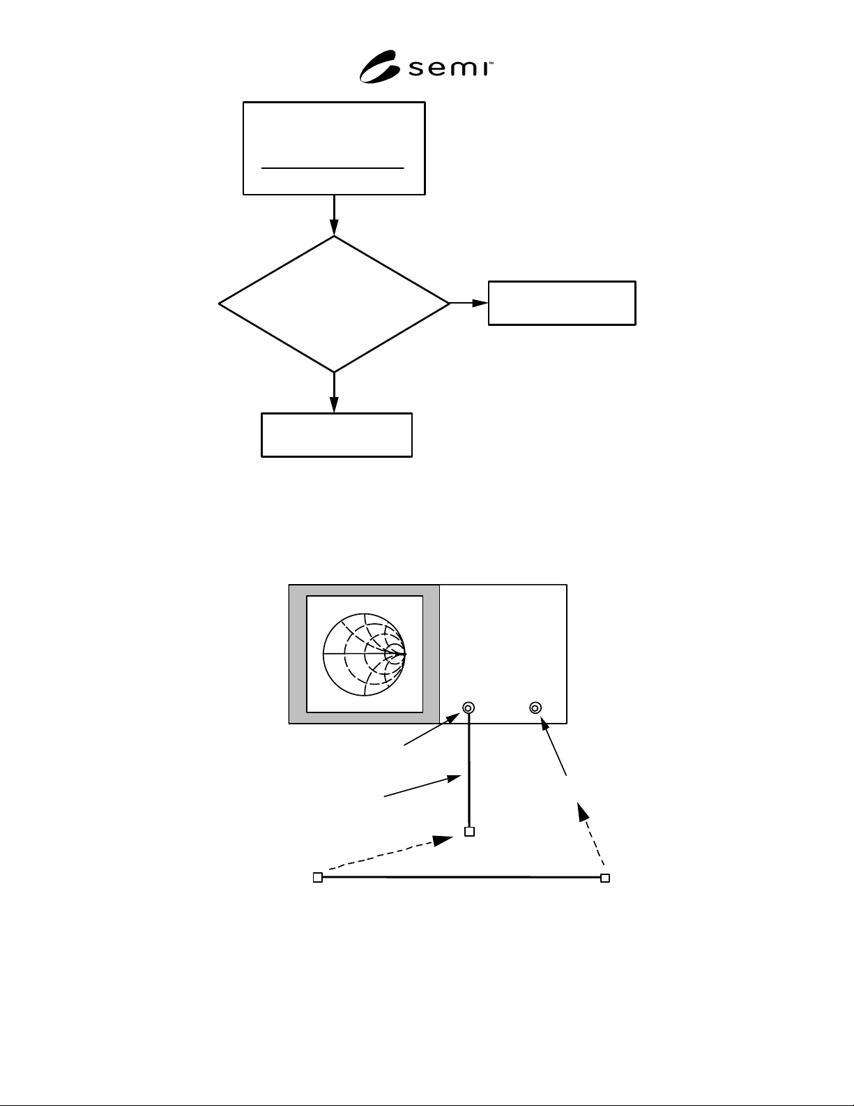
Estimate the
Free-Space Length
of Cable Assembly
Physical Length
Velocity of Propagation
[]
Is the
Estimated Length
Less Than a Quarter Wavelength
at the Nominal Operating
Frequency?
Use Test Method 1
to Measure Wavelength
Use Test Method 2
to Measure Wavelength
Yes
No
Figure 2
Flow Chart Showing the Steps to Chose the Appropriate Test Method for Determining Electrical Length of
the Cable Assembly
Port 1
Port 2
A
dditional Test Cable
Cable Assembly to be tested
Network
A
nal
y
zer
NOTE: Both the Port 1 and Port 2 outputs need to be used for the measurement. An additional test cable is needed for the
transmission calibration between the two ports. The cable assembly to be tested (DUT) attaches between the additional test cable
on Port 1 and Port 2.
Figure 3
Schematic of the Network Analyzer Test Setup for the Power Dissipation (loss) Measurement
SEMI E114-0302
E
© SEMI 2002 7
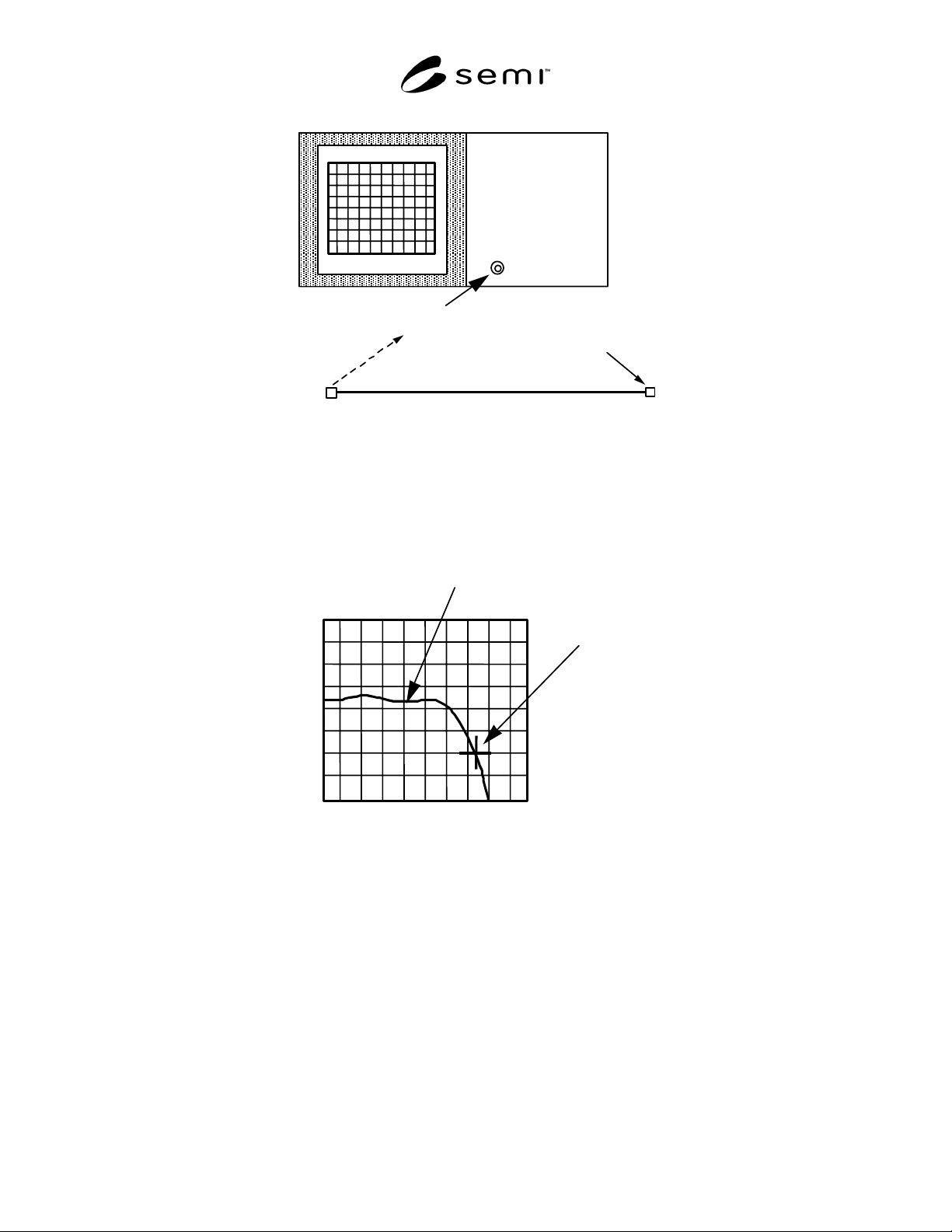
Short Circuit
Termination
Cable Assembly to be tested
Test Port
TDR
NOTE: The cable assembly to be tested (DUT) attaches to the test port and is terminated with a short circuit.
Figure 4
Schematic of the Time Domain Reflectometer (TDR) Test Setup for the Characteristic Impedance
Measurement
Point where impedance
is 45 ohms
50
45
40
55
60
Test Data Curve near
short circuit termination
Distance
Impedance
NOTE: The measurement termination point is defined as where the impedance at the short is equal to 0.9 times the nominal
impedance value, which would be 45 ohms for a 50-ohm nominal impedance.
Figure 5
Example Plot of the Characteristic Impedance of a 50-ohm Cable Assembly Near the Short Circuit
Termination
SEMI E114-0302
E
© SEMI 2002 8
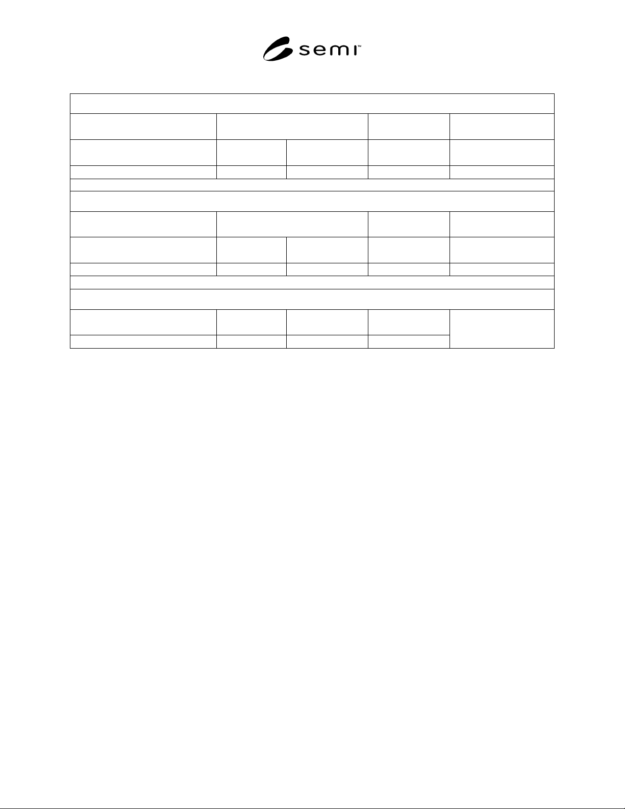
Table 1 Example Data Table for Presenting the Test Methods Parameters
Cable Length Test
Instrument
Parameters
Model Number
Bandwidth
(Hz)
Frequency (MHz) Test Method
(1 or 2)
Cable Assembly
Length (°)
Power Loss Test
Instrument
Parameters
Model Number
Bandwidth
(Hz)
Frequency (MHz) Loss (dB) Power Transferred (%)
Characteristic Impedance Test
Instrument
Model Number
Normalization
Factor
Minimum
Impedance
Maximum
Impedance
NOTICE: SEMI makes no warranties or representations as to the suitability of the standards set forth herein for any
particular application. The determination of the suitability of the standard is solely the responsibility of the user.
Users are cautioned to refer to manufacturer' s instructions, product labels, product data sheets, and other relevant
literature, respecting any materials or equipment mentioned herein. These standards are subject to change without
notice.
By publication of this standard, Semiconductor Equipment and Materials International (SEMI) takes no position
respecting the validity of any patent rights or copyrights asserted in connection with any items mentioned in this
standard. Users of this standard are expressly advised that determination of any such patent rights or copyrights, and
the risk of infringement of such rights are entirely their own responsibility.
Copyright by SEMI® (Semiconductor Equipment and Materials
International), 3081 Zanker Road, San Jose, CA 95134. Reproduction o
f
the contents in whole or in part is forbidden without express writte
n
consent of SEMI.