semi合集-English.pdf - 第873页
SEMI E116-0705 © SEMI 2002, 2005 5 8 Overvie w 8.1 This section defines the concepts that enable EPT to prov ide information required for determining equipment performance. 8.2 Equi pment processi ng tim es, including t …

SEMI E116-0705 © SEMI 2002, 2005 4
Equipment Constants
Alarm Management
6.2 An EPT compliant implementation requires a documented list of all EPT modules contained within the
equipment.
6.3 An EPT compliant implementation requires an EPT state model for the equipment and for each EPT module.
6.4 Each EPT module shall have a documented list of tasks that the module may perform.
7 Conventions
7.1 This document follows the conventions for state model methodology and service definitions used by the SEMI
standards referenced in §4.
7.2 State Model Methodology
7.2.1 A state model has three elements: definitions of each state and sub-state, a diagram of the states showing the
valid transitions between states, and a corresponding state transition table that defines the triggers for each
transition. The diagram of the state model uses the Harel State Chart notation. An overview of this notation is
presented in an Appendix of SEMI E30. The definition of this notation is presented in Science of Computer
Programming 8, “Statecharts: A Visual Formalism for Complex Systems”, by D. Harel, 1987.
7.2.2 Transition tables are provided in conjunction with the state diagrams to explicitly describe the nature of each
state transition. A transition table contains columns for Transition number, Previous State, Trigger, New State,
Actions, and Comments. The “trigger” (column 3) for the transition occurs while in the “previous” state. The
“actions” (column 5) includes a combination of:
1) Actions taken upon exit of the previous state.
2) Actions taken upon entry of the new state.
3) Actions taken that are most closely associated with the transition.
7.2.3 No differentiation is made between these cases.
# PREVIOUS
STATE
TRIGGER NEW STATE ACTIONS COMMENTS
Transition #
7.3 Variable Data Item Definition
7.3.1 The variable item dictionary contained in this document defines the variable name, description, type (format),
access (read/write or read only), and comments about the variable. This is depicted in the format of the following
table:
VARIABLE NAME DESCRIPTION TYPE ACCESS COMMENT
7.4 Event Description
7.4.1 The collection event description table contained in this document includes the event name, the state model
transition, the description, and the data required for the event. This is depicted in the format of the following table:
EVENT NAME STATE MODEL
TRANSITION
NUMBER
DESCRIPTION REQUIRED DATA

SEMI E116-0705 © SEMI 2002, 2005 5
8 Overview
8.1 This section defines the concepts that enable EPT to provide information required for determining equipment
performance.
8.2 Equipment processing times, including throughput and cycle times, are determined by two factors: (1) the
sequence of tasks performed by the equipment’s EPT modules, including the number of each task performed, as well
as the series and parallel relationships between tasks, and (2) the execution time of each individual task. By tracking
equipment systems in terms of modules that perform tasks, it will be possible to precisely identify the affect of both
factors toward overall system performance.
8.3 EPT enables tracking to this level of detail by introducing the concept of an EPT module and the concept of a
task. EPT-compliant equipment are required to report events according to a breakdown of equipment operations
into tasks and EPT modules. An EPT module is an equipment component that affects processing or throughput, and
is capable of executing only one task at a time. Examples of EPT modules include process stations, process
chambers, wafer handling systems, etc. A task is a planned and repeatable activity with an expected duration and a
definite beginning and end. Examples of tasks include the following:
Move wafer from cassette to stage
Pre-align wafer
Align reticle
Preheat chamber
Increase vacuum etc.
8.4 EPT-compliant equipment consist of EPT modules that perform tasks. Thus, the state of the equipment can be
effectively modeled as a composition of the states of the EPT modules. In addition, EPT provides detailed
information required for performance tracking by providing the task-level details for each EPT module.
8.5 EPT modules and tasks are to be defined such that each EPT module executes only one task at a time. An
example is given in Related Information §R1-7. Each equipment system must have defined at least as many EPT
modules as tasks that may be performed simultaneously by that system.
8.6 Each task should be defined such that the units involved (e.g., wafers, substrates, reticles), the EPT modules
involved (e.g., process station, robot, etc.), and the task type (e.g., “process”, “support”, etc.) are constant throughout
the duration of the task. A change in any of the following items should result in the start of a new task or completion
of current task:
Change in material involved (e.g., arrival of wafer, removal of wafer)
Change of EPT modules involved (e.g., robot moves wafer, chamber processes wafer)
Change in task type (e.g., purge recipe followed by production recipe)
NOTE 1: It is not practical for equipment to define tasks or modules at an indefinite level of detail. It is therefore recommended
that in each instance for which the material involved, the EPT modules involved, and the task types are all constant, events for
only one task should be reported. Any further breakdown is not required for EPT compliance. EPT places no limitations on
supplemental event reporting within any task. However, these supplemental events should not be reported as EPT events.
9 EPT State Model
9.1 This section defines the basic Equipment Performance Tracking State Model, which is applied to the equipment
and its EPT modules.
9.2 EPT State Model Requirements
9.2.1 The EPT state model is intended to capture the different states of the equipment and its EPT modules from an
operational point of view:
EPT module busy executing a task.
EPT module blocked from executing a task.
SEMI E116-0705 © SEMI 2002, 2005 6
EPT module idle.
9.2.2 The equipment shall maintain an EPT state model for each major module (e.g., process stations and chambers,
wafer handling systems, etc.) through which a unit passes throughout the entire equipment from removal of units
from the carrier to the return of units to the carrier.
9.2.3 The equipment shall maintain an EPT state model for any major component of the equipment that impacts
processing and throughput.
9.2.4 The equipment shall maintain its own EPT state model for the overall equipment.
9.2.5 The equipment is responsible for communicating all EPT state transitions.
9.2.6 The EPT state model can be applied to the Equipment Front-End Module (EFEM).
9.2.7 There are two types of EPT Modules: (1) Production EPT modules, and (2) EFEM/LoadPort EPT modules.
Both types have a module-level EPT State Machine.
9.3 EPT State Model Diagram
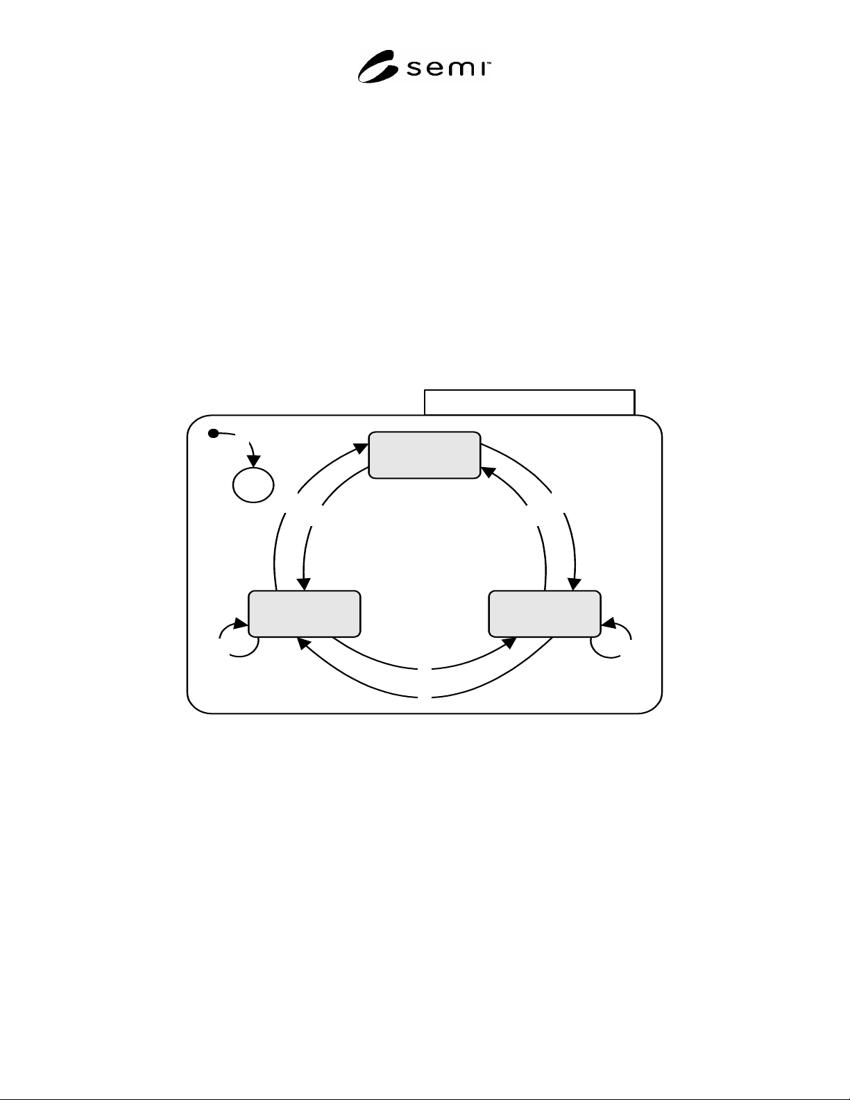
9.3.1 Figure 1 shows the EPT state module diagram.
1
9
4
2
3
7
8
5
6
IDLE
BLOCKED BUSY
EPT State Model
C
Figure 1
Equipment Performance Tracking State Model
9.4 EPT State Definitions
This section describes the EPT states.
9.4.1 IDLE
9.4.1.1 EPT Module — The following conditions are required for the module to be in the IDLE state:
No material is present in the module and
The module is not executing a task and
No fault condition exists in the module that prevents it from starting a new task.
9.4.1.2 Equipment — The following conditions are required for the equipment to be in the IDLE state: