semi合集-English.pdf - 第892页
SEMI E116-0705 © SEMI 2002, 2005 24 R1-7 Operation Scenarios for Carrier Hand ling Module R1-7.1 A coup le of following scenarios are typical fo r different typ e of Carri er Handling Mo dule. R1-7.2 Carrier Handlin g Mo…
SEMI E116-0705 © SEMI 2002, 2005 23
Table R1-6 Triggers of Transitions for Specific Tasks of Carrier Transfer Mechanism in Internal Buffer Unit
# Previous State Trigger New State Action(s) Comment
2 IDLE Transfer Started BUSY Moves carrier to
destination
3 BUSY Transfer Complete IDLE None Ready to unload or remove from
port.
Table R1-7 Triggers of Transitions for specific tasks of Carrier ID Reader
# Previous State Trigger New State Action(s) Comment
2 IDLE Reading Started BUSY None Carrier moving sequence before
reading.
3 BUSY Reading Complete IDLE Verification Processing or moving wafers
between carrier and process
container after opening.
Table R1-8 Triggers of Transitions for Specific Tasks of Carrier ID Writer
# Previous State Trigger New State Action(s) Comment
2 IDLE Writing Started BUSY None Processing wafers before writing.
3 BUSY Writing Complete IDLE Waiting next
writing or any
post writing
action
Carrier moving sequence after
writing.
Table R1-9 Triggers of Transitions for Specific Tasks of FOUP Opener
# Previous State Trigger New State Action(s) Comment
2 IDLE Opening or Closing
Started
BUSY None Carrier moving sequence before
opening.
3 BUSY Opening or Closing
Complete
IDLE None Processing or moving wafers
between carrier and process
container after opening.
Table R1-10 Triggers of Transitions for Specific Tasks of Slot Mapper
# Previous State Trigger New State Action(s) Comment
2 IDLE Scanning Started BUSY None Carrier moving sequence before
mapping.
3 BUSY Scanning Complete IDLE Waiting next
scan
Processing or moving wafers
between carrier and process
container after mapping.
Table R1-11 Triggers of Transitions Common for all Components of Carrier Handling Module
# Previous State Trigger New State Action(s) Comment
1 (no state) Initialization is
complete
IDLE None
7 BLOCKED Get Recovered IDLE None
8 IDLE Unable to do task BLOCKED None
9 BLOCKED Get another Fault BLOCKED None
SEMI E116-0705 © SEMI 2002, 2005 24
R1-7 Operation Scenarios for Carrier Handling Module
R1-7.1 A couple of following scenarios are typical for different type of Carrier Handling Module.
R1-7.2 Carrier Handling Module for Fixed Buffer Type
R1-7.2.1 Beside the number of Loadports, following table shows just one set of components out of them.
R1-7.2.2 Indicated subsystems: PIO = Carrier Handoff PIO Port, CID-R = Carrier ID Reader, X’fer Transfer
Mechanism = Carrier Transfer Mechanism (Docking Mechanism), CID-W = Carrier ID Writer, Opener = FOUP
Opener, Mapper = Carrier Slot Mapper.
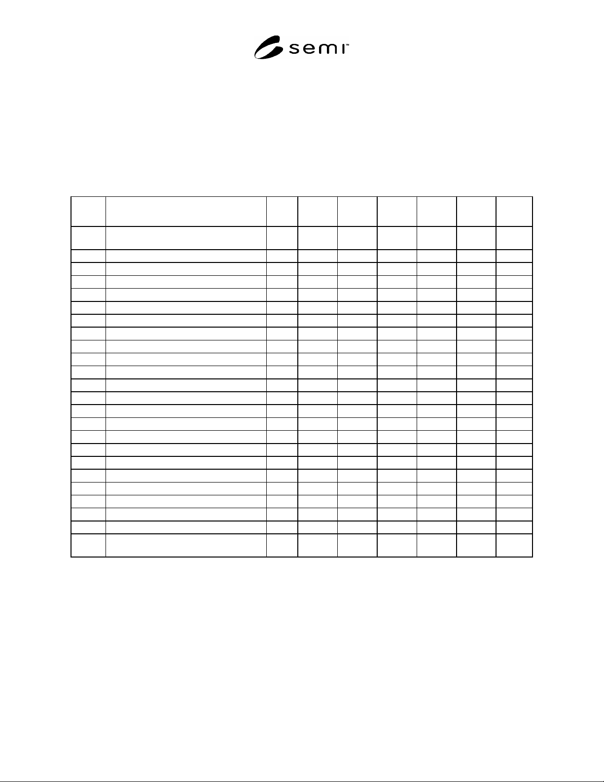
Table R1-12 Scenario of Fixed Type Carrier Handling Module
Event # Description Time PIO CID-R. X’fer
Mech
CID-W Opener Mapper
0 Carrier Handling Module and all
components starting in “IDLE”
0:00 IDLE IDLE IDLE IDLE IDLE IDLE
1 Loading Started 0:30 BUSY
2 Loading Completed 1:00 IDLE
3 ID Reading Started 1:05
BUSY
4 ID Reading Complete 1:10
IDLE
5 ID Verification -
6 Docking Started 1:20
BUSY
7 Docking Complete 1:50
IDLE
8 Opening Start 1:55
BUSY
9 Opening Complete 2:25
IDLE
10 Mapping Started 2:30
BUSY
11 Mapping Complete 2:15
IDLE
12 Slotmap Verification -
13 Process Started 12:15
14 Process Completed 47:15
15 Writing Started 47:20
BUSY
16 Writing Complete 48:10
IDLE
17 Closing Start 48:10
BUSY
18 Closing Complete 48:40
IDLE
19 Undocking Started 48:45
BUSY
20 Undocking Complete 49:15
IDLE
21 Unloading Started 52:25 BUSY
22 Unloading Complete 52:55 IDLE
23 Carrier Handling Module and all
components returning in “IDLE”
52:55
R1-7.3 Carrier Handling Module for Internal Buffer Type
R1-7.3.1 It is assumed that Carrier Slot Mapper and Carrier ID Writer are mounted at an FIMS port next to Internal
Buffer located inside of the equipment. The following table shows the set of components of a single Loadport.
R1-7.3.2 Indicated subsystems: PIO = Carrier Handoff PIO Port, CID-R = Carrier ID Reader, X’fer A = Carrier
Transfer Mechanism from Handoff position to Carrier In/Out position, X’fer B = Carrier Transfer Mechanism of
Internal Buffer, X’fer C = Carrier Transfer Mechanism (Docking Mechanism) for internal FIMS port, CID-W =
Carrier ID Writer, Opener = FOUP Opener, Map = Carrier Slot Mapper
SEMI E116-0705 © SEMI 2002, 2005 25
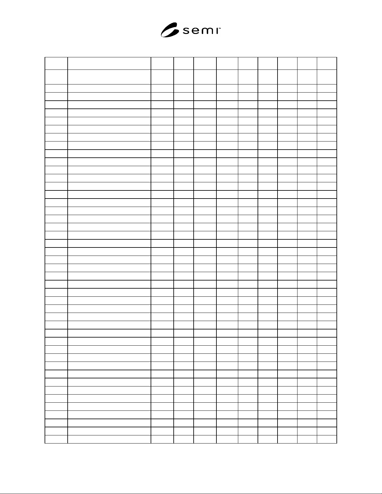
Table R1-13 Scenario of Fixed Type Carrier Handling Module
Event # Description Time PIO CID-R. X’fer A X’fer B X’fer C CID-W Opener Map
0 Carrier Handling Module and all
components starting in “IDLE”
0:00 IDLE IDLE IDLE IDLE IDLE IDLE IDLE IDLE
1 Loading Started 0:30 BUSY
2 Loading Completed 1:00 IDLE
3 ID Reading Started 1:05
BUSY
4 ID Reading Complete 1:10
IDLE
5 ID Verification -
6 Transfer Started 1:20
BUSY
7 Transfer Complete 1:35
IDLE
8 Moving Started 1:40
BUSY
9 Moving Complete 2:25
IDLE
10 Docking Started 2:30
BUSY
11 Docking Complete 2:50
IDLE
12 Opening Start 2:55
BUSY
13 Opening Complete 3:25
IDLE
14 Mapping Started 3:30
BUSY
15 Mapping Complete 3:15
IDLE
16 Slotmap Verification -
17 Wafer Moving Started 3:30
18 Wafer Moving Completed 7:00
12 Closing Start 7:05
BUSY
13 Closing Complete 7:20
IDLE
21 Undocking Started 7:25
BUSY
22 Undocking Complete 7:45
IDLE
8 Moving Started 7:50
BUSY
9 Moving Complete 8:35
IDLE
17 Process Started 16:15
18 Process Completed 147:15
8 Moving Started 146:30
BUSY
9 Moving Complete 147:15
IDLE
10 Docking Started 147:20
BUSY
11 Docking Complete 147:40
IDLE
19 Writing Started 147:45
BUSY
20 Writing Complete 148:10
IDLE
12 Opening Start 148:10
BUSY
13 Opening Complete 148:25
IDLE
17 Wafer Moving Started 148:30
18 Wafer Moving Completed 152:00
12 Closing Start 152:05
BUSY
13 Closing Complete 152:20
IDLE
21 Undocking Started 152:25
BUSY
22 Undocking Complete 152:45
IDLE
23 Moving Started 152:50
BUSY
24 Moving Complete 153:35
IDLE
25 Transferring Started 153:40
BUSY
26 Transferring Complete 153:55
IDLE