semi合集-English.pdf - 第927页
SEMI E118.1-1104 © SEMI 2003, 2004 4 8.3 2D Code Read Condition Attributes 8.3.1 Table 6 specifies the values for the 2D Code Read Condition attribute id entifiers and limitations on values. Table 6 2D Code Read Conditio…
SEMI E118.1-1104 © SEMI 2003, 2004 3
8 Data
8.1 WIDR Attributes
8.1.1 Table 4 specifies the values for the WIDR attribute identifiers and limitations on values.
Table 4 WIDR Attribute Definitions
Attribute Name Description Access Format Value
Fundamental
“Configuration” Number of heads. RO 20
“01”“31”
“AlarmStatus” Current WIDR substate of ALARM STATUS. RO 20 “0” = NO ALARMS
“1” = ALARMS
“OperationalStatus” Current WIDR substate of OPERATIONAL. RO 20 “IDLE”, “BUSY”,
“MANT”
“SoftwareRevisionLevel” Revision (version) of software. RO 20 8 byte maximum
Optional
“DateInstalled” Date the subsystem was installed. RO 20 “YYYYMMDD” format
“DeviceType” Identifies subsystem as a Wafer ID Reader. RO 20 “WIDR”
“HardwareRevisionLevel” Revision number of the hardware. RO 20 8 byte maximum
“MaintenanceData” Supplier dependent. RO 20 80 byte maximum
“Manufacturer” The name or identifier of the manufacturer. RO 20 20 byte maximum
“ModelNumber” The manufacturers model designation. RO 20 20 byte maximum
“SerialNumber” Subsystem serial number assigned by
manufacturer.
RO 20 20 byte maximum
8.2 Read Head Attributes
8.2.1 Table 5 shows the format and values for the Read Head.
Table 5 Read Head Attribute Definitions
Attribute Name Description Access Format Value
Fundamental
“HeadStatus” The current state. RO 20 “IDLE”,
“BUSY”,
“NOOP”
“HeadID” Head number 0–31. RO 20 2 digits, “00” through “31”.
Optional
“HeadCondition” The current Maintenance
status.
RO 20 Enumerated:
“NO” = No alarms
“NM” = Needs maintenance
“NP” = No power
“RW” = Read fault
“HeadDateInstalled” Date this head was installed. RO 20 “YYYYMMDD” format
“HeadMaintenanceData” Supplier dependent. RO 20 Text
SEMI E118.1-1104 © SEMI 2003, 2004 4
8.3 2D Code Read Condition Attributes
8.3.1 Table 6 specifies the values for the 2D Code Read Condition attribute identifiers and limitations on values.
Table 6 2D Code Read Condition Attribute Definitions
Attribute Name Description Access Format Value
Optional
“CellSize” Number of Pixels in a Cell RO 20 “000”–“999”
“Contrast” Contrast Percentage of Dark / Light RO 20 “000”–“100”
“Damage Percent” Percentage of Damage Cell RO 20 “000”–“100”
“Number Error Bits” Number of the Damage Cell RO 20 “000”–“999”
“Read Time” Time for Readout, in seconds RO 20 “000”–“120”
“Matrix Style” Normal Mode or Mirror Mode RO 20 “NO” = Normal Mode
“MR” = Mirror Mode
“Matrix Polarity” Dark on Light or Light on Dark RO 20 “DON” = Dark on Light
“LON” = Light on Dark
To show that data is not available for an attribute, the attribute value is set to a zero-length string.
Note 1: A zero-length item for an attribute value means that does not exist.
NOTICE: SEMI makes no warranties or representations as to the suitability of the standards set forth herein for any
particular application. The determination of the suitability of the standard is solely the responsibility of the user.
Users are cautioned to refer to manufacturer's instructions, product labels, product data sheets, and other relevant
literature, respecting any materials or equipment mentioned herein. These standards are subject to change without
notice.
By publication of this standard, Semiconductor Equipment and Materials International (SEMI) takes no position
respecting the validity of any patent rights or copyrights asserted in connection with any items mentioned in this
standard. Users of this standard are expressly advised that determination of any such patent rights or copyrights, and
the risk of infringement of such rights are entirely their own responsibility.
SEMI E118.1-1104 © SEMI 2003, 2004 5
RELATED INFORMATION 1
SCENARIOS
NOTICE: This related information is not an official part of SEMI E118.1 and was derived from the work of the
originating task force. This related information was approved for publication by full letter ballot procedures on
January 10, 2003.
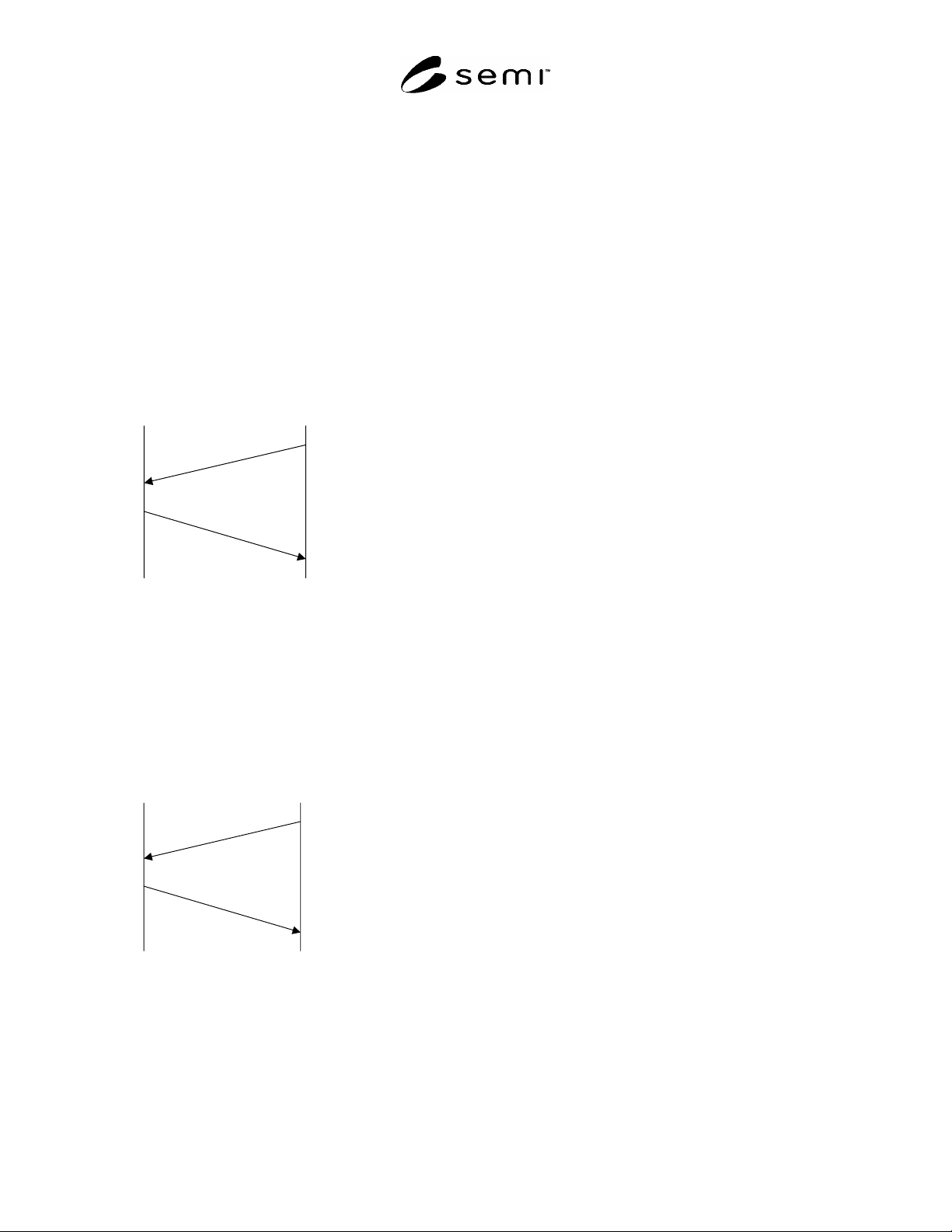
This section provides examples of typical scenarios for a Wafer ID Reader.
R1-1 Read WID
R1-1.1 The upstream controller sends a Read WID
Request message to the WIDR for Head 1. The WIDR
Head 1 reads the ID, and the WIDR returns the ID to
the upstream controller.
WIDR
Upstream
Controller
S18, F9 Read ID Request
Target ID = “01”
S18, F10 Read ID Data
MID = “XYZ001”
Figure R1-1
Read WID Scenario
R1-2 Read WID
R1-2.1 The upstream controller sends a Read WID
Request message to the WIDR for Head 1. The WIDR
Head 1 reads the ID, but the WIDR can't read the ID.
There isn't the ID on the wafer.
WIDR
Upstream
Controller
S18, F9 Read ID Request
Target ID = “01”
S18, F10 Read ID Data
Rsult Status = “EE”
MID = “”
Figure R1-2
Read WID Scenario
NOTICE: SEMI makes no warranties or
representations as to the suitability of the standards set
forth herein for any particular application. The
determination of the suitability of the standard is solely
the responsibility of the user. Users are cautioned to
refer to manufacturer's instructions, product labels,
product data sheets, and other relevant literature,
respecting any materials or equipment mentioned
herein. These standards are subject to change without
notice.
By publication of this standard, Semiconductor
Equipment and Materials International (SEMI) takes no
position respecting the validity of any patent rights or
copyrights asserted in connection with any items
mentioned in this standard. Users of this standard are
expressly advised that determination of any such patent
rights or copyrights, and the risk of infringement of
such rights are entirely their own responsibility.
Copyright by SEMI® (Semiconductor Equipment and Materials
International), 3081 Zanker Road, San Jose, CA 95134. Reproduction of
the contents in whole or in part is forbidden without express written
consent of SEMI.