00197674-01-UM-E-Series-EN-05-2015.pdf - 第127页
User manual SIPLACE E 3 Technical data and assemblies From software version SC 708.0 05/2015 Edition 3 .5 Placement hea d 127 3.5.4.1 Safety instructions 3 3 WARNING Please obser ve the wa rning label sec tion 2.2.5 , …
3 Technical data and assemblies User manual SIPLACE E
3.5 Placement head From software version SC 708.0 05/2015 Edition
126
3.5.4 Vacuum pump
Each Collect&Place head (SIPLACE CP14/12/6) has its own vacuum generator, which supplies
the holding and placement circuit with the required vacuum. The vacuum generator for the place
-
ment heads functions according to the Venturi principle. When operated together with a vacuum
pump, the Collect&Place head (SIPLACE CP14/12/6) reduce the compressed air consumption
considerably. The running costs will fall according to the energy costs incurred.
3
3
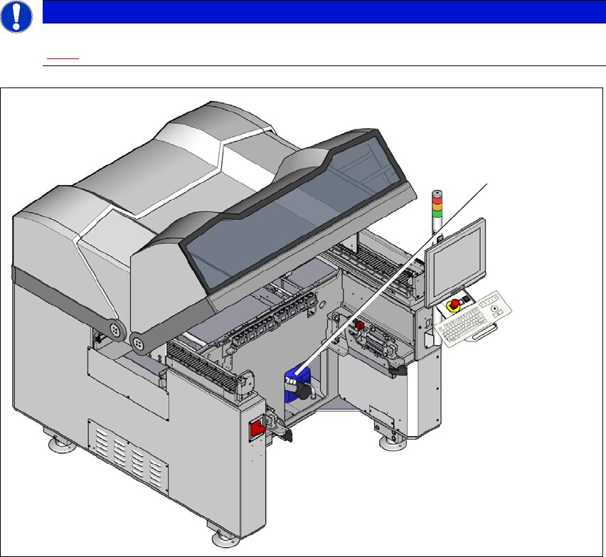
Fig. 3.5 - 7 Location of the vacuum pump
(1) Location of the vacuum pump
PLEASE NOTE
The compressed air consumption values with the vacuum pump can be found in section
3.2.4
, page 103.
(1)

User manual SIPLACE E 3 Technical data and assemblies
From software version SC 708.0 05/2015 Edition 3.5 Placement head
127
3.5.4.1 Safety instructions
3
3
WARNING
Please observe the warning label section 2.2.5, page 58.
WARNING
Please observe the safety instructions of the vacuum pump in the user manual sup
-
plied.
3 Technical data and assemblies User manual SIPLACE E
3.5 Placement head From software version SC 708.0 05/2015 Edition
128
3.5.5 SIPLACE TH for high precision IC placement
Item no. 03033629-xx SIPLACE TH
Item no. 03112312-xx Stationary component camera, type 36 GigE
3
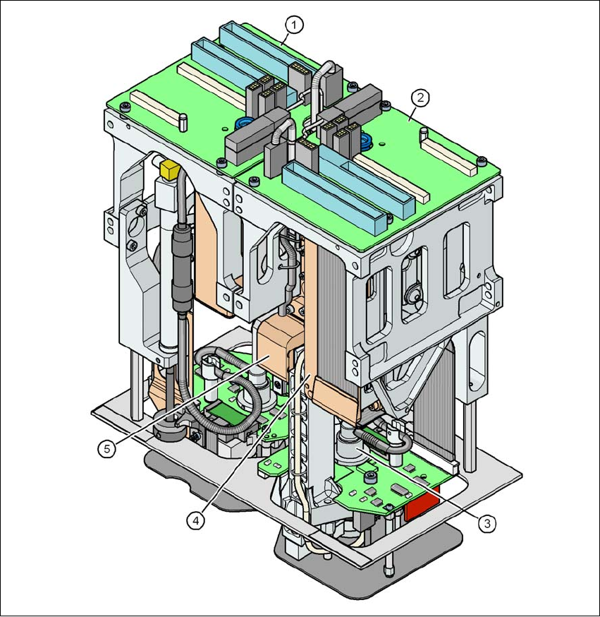
Fig. 3.5 - 8 SIPLACE TH for high precision IC placement
(1) Pick&Place module 1 (PP1) - the SIPLACE TH consists of 2 Pick&Place modules
(2) Pick&Place module 2 (PP2)
(3) DP axis
(4) Z axis drive
(5) Incremental distance measuring system for the Z axis