00197674-01-UM-E-Series-EN-05-2015.pdf - 第132页
3 Technical data and assemblies User manual SIPLACE E 3.5 Placement head From software version SC 708.0 05/2015 Editio n 132 3.5.6.1 Description This highly sophisticated placement head w orks on the Pick&Plac e prin…
User manual SIPLACE E 3 Technical data and assemblies
From software version SC 708.0 05/2015 Edition 3.5 Placement head
131
3.5.6 SIPLACE PP for high-precision IC placement
Item no. 03097485-xx SIPLACE PP
Item no. 03112312-xx Stationary component camera, type 36 GigE
3
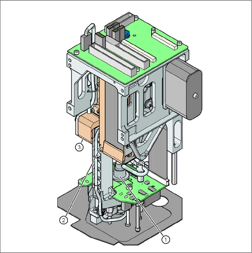
Fig. 3.5 - 9 SIPLACE PP for high-precision IC placement
(1) DP axis
(2) Z axis drive
(3) Incremental distance measuring system for the Z axis
3 Technical data and assemblies User manual SIPLACE E
3.5 Placement head From software version SC 708.0 05/2015 Edition
132
3.5.6.1 Description
This highly sophisticated placement head works on the Pick&Place principle. The SIPLACE PP is
suitable for processing particularly difficult or large components. The components are picked up
by the placement head, optically centered on the way to the placement position and rotated into
the necessary placement angle. They are then placed gently and accurately onto the PCB with a
controlled blast of air.
The nozzles of type 5xx/5xxx have been developed for the SIPLACE PP. With an adapter you can
also use the nozzles of type 4xx, 8xx and 9xx.
User manual SIPLACE E 3 Technical data and assemblies
From software version SC 708.0 05/2015 Edition 3.5 Placement head
133
3.5.6.2 Technical data
3
SIPLACE PP
with stationary
camera type 36 GigE
(Standard)
with stationary
camera type 33 GigE
(Fine pitch)
with stationary
camera type 25 GigE
(Flip chip)
Range of components
*a
*)a Please note that the range of components that can be placed is also affected by the pad geometry, customer-
specific standards, component packaging tolerances and component tolerances.
0603 to SO, PLCC,
QFP, BGA, special
components, bare dies,
flip-chips
0402 to SO, PLCC,
QFP, BGA, special
components, bare dies,
flip-chips
0201 to SO, PLCC,
QFP, sockets, plugs,
BGA, special compo
-
nents, bare dies, flip-
chips, shields
Component specification
Max. height
*b
Min. lead pitch
Min. lead width
Min. ball pitch
Min. ball diameter
Min. dimensions
Max. dimensions
Max. weight
*c
*)b 19 mm if one nozzle of the CP12/CP6 is removed. 8.5 mm if no nozzle of the CP12/CP6 is removed.
*)c If standard nozzles are used
19 mm
0.4 mm
0.24 mm
0.56 mm
0.32 mm
1.6 mm x 0.8 mm
32 mm x 32 mm
(single measurement)
45 mm x 98 mm
100 g
19 mm
0.3 mm
0.15 mm
0.35 mm
0.2 mm
1.0 mm x 0.5 mm
55 mm x 45 mm
(single measurement)
45 mm x 98 mm
100 g
19 mm
0.25 mm
0.1 mm
0.14 mm
0.08 mm
0.6 mm x 0.3 mm
16 mm x 16 mm
(single measurement)
100 g
Programmable set-down
force 1.0 N - 15 N 1.0 N - 15 N 1.0 N - 15 N
Nozzle types 5xx (standard)
4xx + adapter
8xx + adapter
9xx + adapter
5xx (standard)
4xx + adapter
8xx + adapter
9xx + adapter
5xx (standard)
4xx + adapter
8xx + adapter
9xx + adapter
X/Y accuracy
*d
*)d The accuracy value was measured using the vendor-neutral IPC standard
± 50 µm/3σ ± 50 µm/3σ ± 37.5 µm/3σ
Angular accuracy ± 0.053°/3σ ± 0.053°/3σ ± 0.053°/3σ
Illumination levels 6 6 6
Possible illumination level
settings
256
6
256
6
256
6