00197674-01-UM-E-Series-EN-05-2015.pdf - 第133页
User manual SIPLACE E 3 Technical data and assemblies From software version SC 708.0 05/2015 Edition 3 .5 Placement hea d 133 3.5.6.2 Technical data 3 SIPLACE PP with statio nary camera type 36 GigE (Standard) with stat …
3 Technical data and assemblies User manual SIPLACE E
3.5 Placement head From software version SC 708.0 05/2015 Edition
132
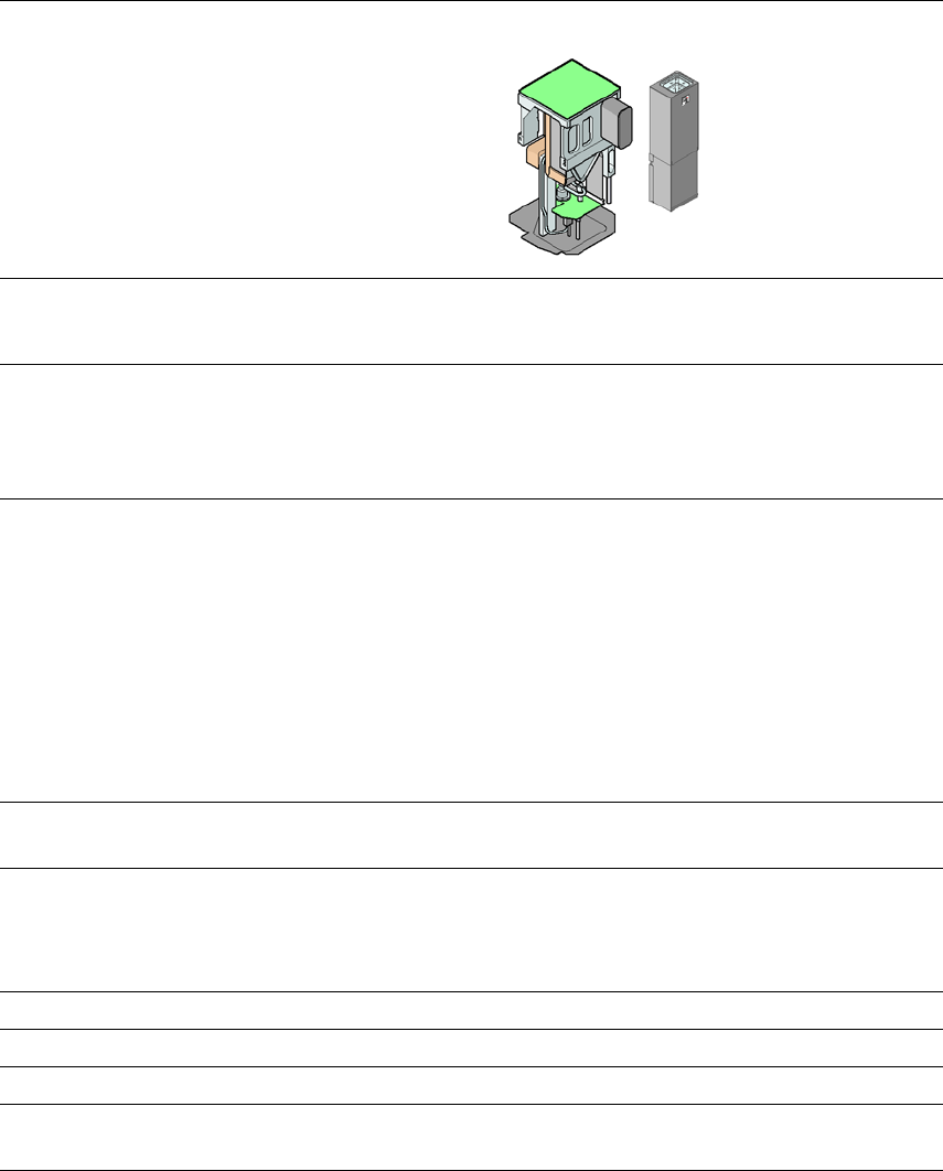
3.5.6.1 Description
This highly sophisticated placement head works on the Pick&Place principle. The SIPLACE PP is
suitable for processing particularly difficult or large components. The components are picked up
by the placement head, optically centered on the way to the placement position and rotated into
the necessary placement angle. They are then placed gently and accurately onto the PCB with a
controlled blast of air.
The nozzles of type 5xx/5xxx have been developed for the SIPLACE PP. With an adapter you can
also use the nozzles of type 4xx, 8xx and 9xx.
User manual SIPLACE E 3 Technical data and assemblies
From software version SC 708.0 05/2015 Edition 3.5 Placement head
133
3.5.6.2 Technical data
3
SIPLACE PP
with stationary
camera type 36 GigE
(Standard)
with stationary
camera type 33 GigE
(Fine pitch)
with stationary
camera type 25 GigE
(Flip chip)
Range of components
*a
*)a Please note that the range of components that can be placed is also affected by the pad geometry, customer-
specific standards, component packaging tolerances and component tolerances.
0603 to SO, PLCC,
QFP, BGA, special
components, bare dies,
flip-chips
0402 to SO, PLCC,
QFP, BGA, special
components, bare dies,
flip-chips
0201 to SO, PLCC,
QFP, sockets, plugs,
BGA, special compo
-
nents, bare dies, flip-
chips, shields
Component specification
Max. height
*b
Min. lead pitch
Min. lead width
Min. ball pitch
Min. ball diameter
Min. dimensions
Max. dimensions
Max. weight
*c
*)b 19 mm if one nozzle of the CP12/CP6 is removed. 8.5 mm if no nozzle of the CP12/CP6 is removed.
*)c If standard nozzles are used
19 mm
0.4 mm
0.24 mm
0.56 mm
0.32 mm
1.6 mm x 0.8 mm
32 mm x 32 mm
(single measurement)
45 mm x 98 mm
100 g
19 mm
0.3 mm
0.15 mm
0.35 mm
0.2 mm
1.0 mm x 0.5 mm
55 mm x 45 mm
(single measurement)
45 mm x 98 mm
100 g
19 mm
0.25 mm
0.1 mm
0.14 mm
0.08 mm
0.6 mm x 0.3 mm
16 mm x 16 mm
(single measurement)
100 g
Programmable set-down
force 1.0 N - 15 N 1.0 N - 15 N 1.0 N - 15 N
Nozzle types 5xx (standard)
4xx + adapter
8xx + adapter
9xx + adapter
5xx (standard)
4xx + adapter
8xx + adapter
9xx + adapter
5xx (standard)
4xx + adapter
8xx + adapter
9xx + adapter
X/Y accuracy
*d
*)d The accuracy value was measured using the vendor-neutral IPC standard
± 50 µm/3σ ± 50 µm/3σ ± 37.5 µm/3σ
Angular accuracy ± 0.053°/3σ ± 0.053°/3σ ± 0.053°/3σ
Illumination levels 6 6 6
Possible illumination level
settings
256
6
256
6
256
6
3 Technical data and assemblies User manual SIPLACE E
3.6 PCB conveyor system From software version SC 708.0 05/2015 Edition
134
3.6 PCB conveyor system
3.6.1 Description
The PCB conveyors are designed as three-part conveyors with input, processing and output con
-
veyor sections. The input and output conveyor areas act as bumper zones for the boards in the
event of short waiting periods. For PCB-Detection sonar sensors are provided in the input, pro
-
cessing and output area.
The PCB is stopped respectively in each area (processing area as well as buffers) by mechanical
stoppers, which are mounted along the conveyor rail. The conveyor rail can be rotated 180° and
use for opposite PCB flow direction. Right side or left side fixed is achieved by rotating the ma
-
chine with 180° and changing the moving direction of the boards.
Item no. 03108391-xx Fixed conveyor rail right E
Item no. 003110457-xx Fixed conveyor rail left E
As soon as the circuit board has reached its target position, the conveyor belt is stopped and the
board is clamped.
The width of the circuit board conveyor is set and monitored by the station software.
The conveyor height can be selected on the machine to allow the machines to be integrated into
lines with a conveyor height of, 900 to 930 or 950 mm. The standard height is 930 mm.
The PCB conveyors communicate with the individual machines via the SMEMA interface.