00197674-01-UM-E-Series-EN-05-2015.pdf - 第206页
5 Working with the machine User manual SIPLACE E 5.6 The user interface From software version SC 708.0 05/2015 Ed ition 206 5.6 The user interface The user interface is div ided into the following ar eas. The user interf…
User manual SIPLACE E 5 Working with the machine
From software version SC 708.0 05/2015 Edition 5.5 Opening and closing the protective covers
205
5.5 Opening and closing the protective covers
The protective covers are electrically and mechanically locked and cannot be opened during op
-
eration.
Opening the protective covers 5
Press the stop button to open the protective cover.
– A message is issued at the station software stating that the protective covers can be
opened.
– The protective covers are mechanically released and can be opened.
Closing the protective covers 5
Close the protective covers.
Press the start button.
– The protective covers are mechanically locked and can no longer be opened.
See also Section 2.5.1 on page 68.
5 Working with the machine User manual SIPLACE E
5.6 The user interface From software version SC 708.0 05/2015 Edition
206
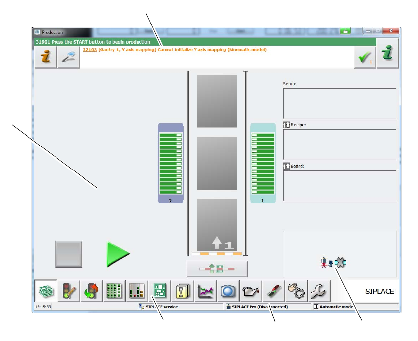
5.6 The user interface
The user interface is divided into the following areas.
The user interface with the "Production" view for the SIPLACE E machine is shown as an exam
-
ple.
5
Fig. 5.6 - 1 User interface components in the "Production state" view (example)
Legend
(1) Status field (status and error display)
(2) View of changed configurations and additional options
(3) Information line
(4) Toolbar
(5) Processing area / display area
(1)
(5)
(4)
(3)
(2)
User manual SIPLACE E 5 Working with the machine
From software version SC 708.0 05/2015 Edition 5.6 The user interface
207
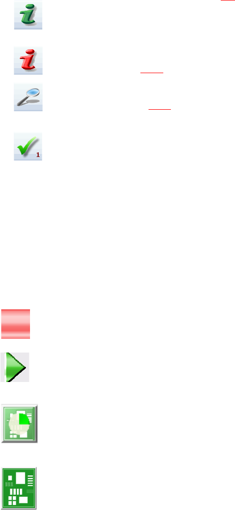
5.6.1 Status field
The status field shows the current machine status, the error which occurred most recently and the
action to be performed (see section 5.7
, page 214).
(Green) Starts the context-sensitive Online Help function for the current view. All operating con
-
trols for the current view are explained
(Red) Starts the help system, showing the possible causes of the current errors and suitable solu
-
tions (see section 5.7.1
, page 215).
Opens a dialog box in which the error source, error message text and the error date with time are
shown (see section 5.7.1
, page 215). The help function for the current error can also be opened
from here.
Deletes the error currently shown from the status field.
5.6.2 Display and processing area
This area shows the buttons for setting/deleting functions, general information about the board,
setup, recipes and other information.
Animated and color-coded items helps explain processes or states (e.g. editing, empty location
etc.).
The "Production" (basic view) view indicates certain operating states (editing, error etc.).
Stop processing. This stops the current processing run.
Continue processing. This starts or continues board placement.
Placement progress
The placement progress is shown for each board on the chart view.
Boards being processed
The board is taken up by the system and placed. The PCB icon will be shown as a dark green
button.