00197674-01-UM-E-Series-EN-05-2015.pdf - 第299页
User manual SIPLACE E 6 Station extensions From software version SC 708.0 05/2015 Edition 6.8 Power Supply COT E 299 6.8 Power Supply COT E Item no. 03114427-xx Power Supply COT E 6 Fig. 6.8 - 1 Power Supply COT E (1) Ha…
6 Station extensions User manual SIPLACE E
6.7 SIPLACE Preparation Table E From software version SC 708.0 05/2015 Edition
298
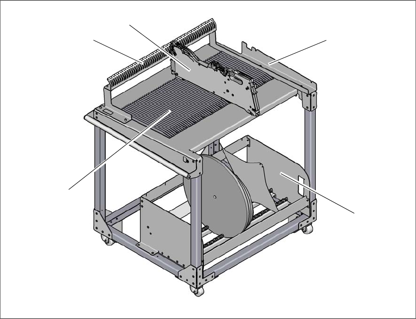
6.7 SIPLACE Preparation Table E
Item no. 03112358-xx SIPLACE Preparation Table E
The SIPLACE Preparation Table E can hold a maximum of 60x SIPLACE SmartFeeder 8 mm E-
with component reel (size 7”, 10”, 13”, 15” & 17”). Feeders can be placed from the top or slid along
the extruded guide profiles. Align each feeder by inserting feeder stop pin into the slots of the
guide plate. SIPLACE Preparation Table E allows SIPLACE PowerAdaptor E to be attached and
detached without tools.
6
Fig. 6.7 - 1 SIPLACE Preparation Table E
(1) Guide profile
(2) Feeder parking unit
(3) SIPLACE SmartFeeder E
(4) Mounting interface for SIPLACE PowerAdaptor E
(5) Tape reel container
(4)
(3)
(2)
(5)
(1)
User manual SIPLACE E 6 Station extensions
From software version SC 708.0 05/2015 Edition 6.8 Power Supply COT E
299
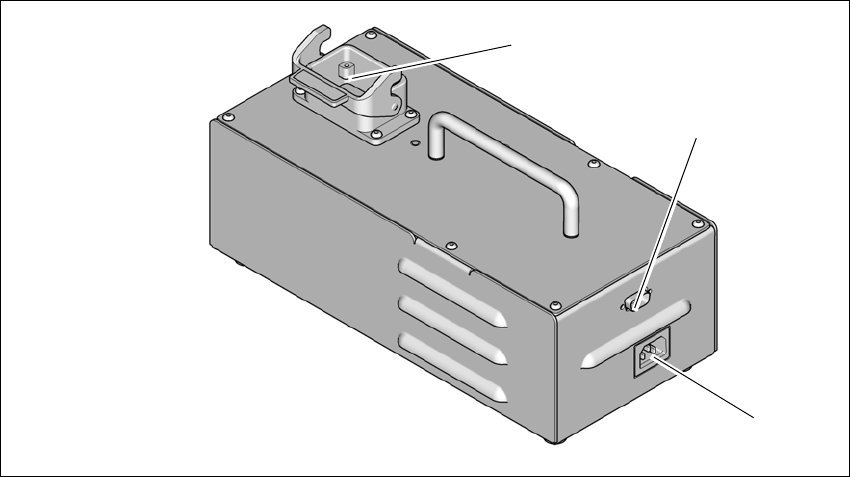
6.8 Power Supply COT E
Item no. 03114427-xx Power Supply COT E
6
Fig. 6.8 - 1 Power Supply COT E
(1) Harting connection
(2) D-sub connection
(3) Power connection
Harting connection
The PowerSupply COT E provides 25V 10A power output to the E series changeover table (COT)
through the Harting connector. Data transfer is also available through this connection, so commu
-
nication with the feeders on the changeover table is possible.
D-sub connection
The D-sub connector is used to connect to the Setup Centre through the CAN bus cable. This al
-
lows the user to program and setup the feeders on the changeover table at a remote location,
away from the placement machine.
Power connection
The module comes with 2 power cords for connection to wall outlet. Depending on the type of wall
socket available in your region, please choose the correct power cords. The AC inlet accepts a
wide range of voltages and frequencies (100-240 VAC, 50-60 Hz).
After powering on the module, the green LED on the top cover of the module will light up.
(3)
(2)
(1)

6 Station extensions User manual SIPLACE E
6.8 Power Supply COT E From software version SC 708.0 05/2015 Edition
300
6
PLEASE NOTE
Connection to the SIPLACE Setup Center
Only one PowerSupply COT E with Change over table is to be connected to SIPLACE
Setup Center for feeder setup.
When using the CAN Bus Cable 03040465-xx with SIPLACE Setup Center, the ter
-
minal resistor at the bus system end to the SIPLACE Setup Center must be acti
-
vated.The terminal resistor at the bus system end to the PowerSupply COT E and
Change over table must NOT be activated.
The CAN ID for the PowerSupply COT E with Change over table in standalone mode
is 0x0518.