00197674-01-UM-E-Series-EN-05-2015.pdf - 第82页
2 Operational safety User manual SIPLACE E 2.7 Safety features From software version SC 708.0 05/2015 Editi on 82 2.7.3 Safety contactors 2 Fig. 2.7 - 5 Overview of the safety contactors 2 (1) Safety unit (behind cover) …
User manual SIPLACE E 2 Operational safety
From software version SC 708.0 05/2015 Edition 2.7 Safety features
81
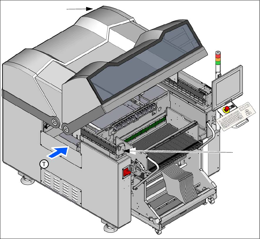
2.7.2.2 Position of protective switches on the machine
2
Fig. 2.7 - 4 Position of protective switches on the machine
(1) Protective cover switch, location 1
(2) Protective cover switch, location 2
Protective cover switch 1 and 2 (item 1 and 2 in fig. 2.7 - 4, page 81) 2
These switches check whether the protective covers are closed. When they are closed, the
EMERGENCY STOP contact and the signaling contact are closed. After pressing the Start button
the covers are locked.
(1)
(2)
2 Operational safety User manual SIPLACE E
2.7 Safety features From software version SC 708.0 05/2015 Edition
82
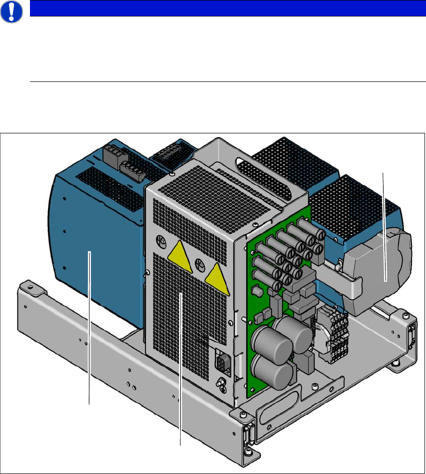
2.7.3 Safety contactors
2
Fig. 2.7 - 5 Overview of the safety contactors
2
(1) Safety unit (behind cover)
(2) Capacitor module
(3) Safety relay
PLEASE NOTE
The protective covers are electrically and mechanically locked
During operation, the protective covers are locked and cannot be opened.
Press the stop button. The protective covers can be opened.
See also Section 2.5 on page 68.
(1)
(2)
(3)

User manual SIPLACE E 2 Operational safety
From software version SC 708.0 05/2015 Edition 2.7 Safety features
83
2
WARNING
Safety instructions about lethal voltages!
Always follow the safety instructions concerning potentially lethal voltages - even when
the machine is switched off. (See section 2.8.1
from page 88).