00197674-01-UM-E-Series-EN-05-2015.pdf - 第83页
User manual SIPLACE E 2 Operational safety From software version SC 708.0 05/2015 Edition 2.7 Safety features 83 2 WARNING Safety instructions a bout lethal voltages! Always follow the safety instruc tions concerning pot…
2 Operational safety User manual SIPLACE E
2.7 Safety features From software version SC 708.0 05/2015 Edition
82
2.7.3 Safety contactors
2
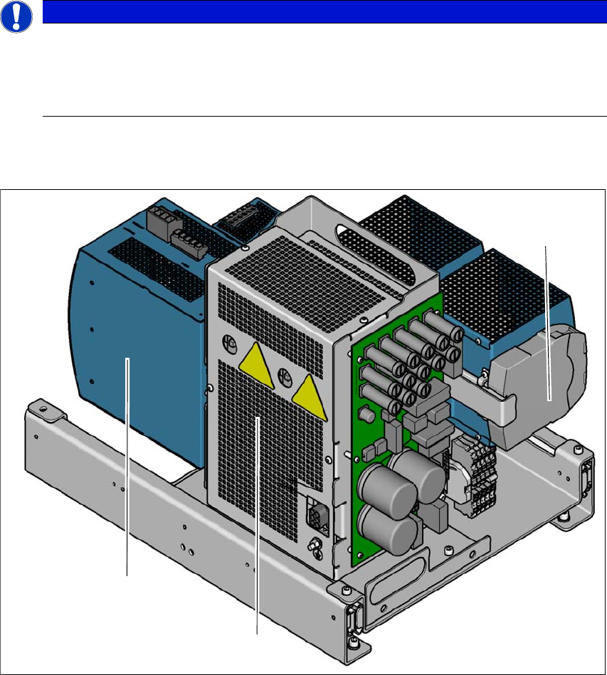
Fig. 2.7 - 5 Overview of the safety contactors
2
(1) Safety unit (behind cover)
(2) Capacitor module
(3) Safety relay
PLEASE NOTE
The protective covers are electrically and mechanically locked
During operation, the protective covers are locked and cannot be opened.
Press the stop button. The protective covers can be opened.
See also Section 2.5 on page 68.
(1)
(2)
(3)
User manual SIPLACE E 2 Operational safety
From software version SC 708.0 05/2015 Edition 2.7 Safety features
83
2
WARNING
Safety instructions about lethal voltages!
Always follow the safety instructions concerning potentially lethal voltages - even when
the machine is switched off. (See section 2.8.1
from page 88).
2 Operational safety User manual SIPLACE E
2.7 Safety features From software version SC 708.0 05/2015 Edition
84
Safety contactors (item 1 in fig. 2.7 - 5, page 82) 2
The safety unit (1) is located inside the power unit. It is used the safety relay (2) to monitor EMER
-
GENCY STOP circuits and to control safety related output voltages (2).
There are three conditions that must be fulfilled in order to activate the safety contactors:
– The "software release" or "Control ON" signal must be issued.
– The EMERGENCY STOP loop must be closed.
– The start button must have been pressed.
2.7.4 EMERGENCY STOP loops and signaling circuit
2.7.4.1 EMERGENCY STOP loop structure
The following contacts are connected in series and form the EMERGENCY STOP loop:
– Make contact elements for the two protective cover switches
– Normally open (NO) contacts for the two EMERGENCY STOP buttons
– Make contact elements for the two changeover tables
2.7.4.2 Signaling circuit structure
The following modules in the signaling circuit are queried individually:
– The protective cover switches
– Signaling contacts on the changeover table
– EMERGENCY STOP button
All the signaling contacts are closed when the machine is on standby. If a protective cover, for
example, is lifted up, the associated signaling contact opens. This change of state is signaled to
the control computer via the CAN bus. An error message to this effect appears on the user inter
-
face.
2.7.4.3 Description of the functions of the EMERGENCY STOP loops
The following conditions must be fulfilled in order to start and operate the machine:
– All changeover tables must be docked in and connected.
– All protective covers must be closed.
– Both emergency stop buttons must be released.
– The minimum operating pressure must have been reached.
– The software release ("Control ON") must be enabled, so that the start signal from the
"Start" button can activate the safety relay and safety units.
If one of the start buttons is now pressed, the safety contactors will be switched-on and the
machine is ready to use.