00197674-01-UM-E-Series-EN-05-2015.pdf - 第86页
2 Operational safety User manual SIPLACE E 2.7 Safety features From software version SC 708.0 05/2015 Editi on 86 2.7.5 Hand guard (Dummy Feeder E) 2.7.5.1 Hand guard (Dummy Feeder E) at the locations The hand guard is t…
User manual SIPLACE E 2 Operational safety
From software version SC 708.0 05/2015 Edition 2.7 Safety features
85
2
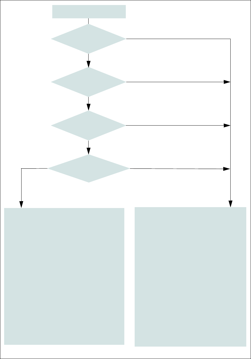
Fig. 2.7 - 6 EMERGENCY STOP loop for SIPLACE E
Start button pressed
No
No
Yes
No
No
Yes
Yes
2
Active
Safety contactors No
Voltage
Y axis 0 V-
X axis 0 V-
Star axis 0 V-
DP axis 42 V-
Z axis (CP) 42 V-
Z axis (TH) 42 V-
Active
PCB conveyor No
Lifting table No
PCB clamping No
Width adjustment No
Tape cutter No
Changeover table feeding device Yes
Yes
Compressed
air min. 0.5 MPa
(5.0 bar)?
EMERGENCY STOP button
pressed?
- Protective cover open?
Changeover table
EMERGENCY STOP circuit
interrupted?
2
Active
Safety contactors Yes
Voltage
Y axis 300 V-
X axis 300 V-
Star axis 160 V-
DP axis 42 V-
Z axis (CP) 42 V-
Z axis (TH) 160 V-
Active
PCB conveyor Yes
Lifting table Yes
PCB clamping Yes
Width adjustment Yes
Tape cutter. Yes
Changeover table feeding device Yes
2 Operational safety User manual SIPLACE E
2.7 Safety features From software version SC 708.0 05/2015 Edition
86
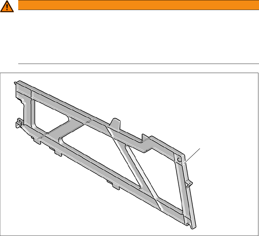
2.7.5 Hand guard (Dummy Feeder E)
2.7.5.1 Hand guard (Dummy Feeder E) at the locations
The hand guard is to be used when there is a gap in between feeders on the component table.
Slot the hand guard in the gap between feeders.
Push the hand guard until it touches the stop rail and the back of the feeder is in line with other
feeders.
2
Fig. 2.7 - 7 Dummy feeder E on the table locations
(1) Dummy feeder SIPLACE E, item no. 03113786-xx
WARNING
Operational
Operational safety by occupying every second location!
The operational safety of the fixed table or changeover table in the SIPLACE E is ensured
if at least every second free location is occupied with a feeder module or hand guard (dum
-
my feeder).
Even when configuring manual tray carriers or a automatic tray changer, secure ev
-
ery second location with a hand guard (dummy feeder).
(1)
User manual SIPLACE E 2 Operational safety
From software version SC 708.0 05/2015 Edition 2.8 Residual voltages and discharge times in the machine
87
2.8 Residual voltages and discharge times in the machine
2
2
DANGER
Dangerous voltage levels!
The machine is supplied with 3 x 200 V~, up to 3 x 415 V~ mains voltage.
This means that some parts of the system carry potentially lethal voltages - even when
switched off at the main power switch.
Incorrect handling of this machine can therefore result in death or severe injury or consid
-
erable damage to equipment.
Always follow the applicable accident prevention and DIN regulations (particularly EN
60204, part 1 or IEC 60204, part 1) and the applicable regulations in your own coun
-
try.
The covers of the power supply unit may ONLY be opened by appropriately qualified
personnel.
CAUTION
Data loss!
To avoid losing data, assess the following criteria before switching off your machine (apart
from in emergencies):
– Has the machine finished transmitting machine, setup and panel data?
– Has the machine finished processing the PCB?
– Has the machine completed the run-up phase?