Gemini Semi Appendix Manual.pdf - 第27页
INSTALLATION APPENDIX SEMI - LEVELS OF ELECTRICAL WORK Chapter Issue 1 Feb 15 Appendix to Micron Technical Manuals 2.9 SEMI - LEVELS OF ELECTRICAL WORK The table be low show the four levels of energized electrical work c…
INSTALLATION APPENDIX
SAFETY FEATURES
2.8 Appendix to Micron Technical Manuals Chapter Issue 1 Feb 15
Pneumatic Lockout
WARNING
COMPRESSED AIR. COMPRESSED AIR SHOULD NEVER IMPINGE UPON THE
BODY. PORTS, PIPES, ETC MUST NEVER BE BLOCKED BY HAND. BEFORE
CONNECTING OR DISCONNECTING ANY PNEUMATIC COMPONENTS, ENSURE
THE COMPRESSED AIR SUPPLY HAS BEEN DISSIPATED AND DISCONNECTED
FROM THE MACHINE.
Pneumatic lockout of the machine is achieved by:
1. If the electrical lockout procedure has just been implemented, go to Step 4.
2. Close down the machine software.
3. Switch the electrical mains isolator to the OFF position.
4. Turn OFF and lockout the factory’s main pneumatic supply to the machine.
5. Pressurised air remaining in the pneumatic supply line is vented via the
pneumatic dump valve.
6. Check the pneumatic pressure gauge to confirm all pressurised air has been
vented.
7. Disconnect the pneumatic supply line from the machine.
8. This completes the pneumatic lockout.
INSTALLATION APPENDIX
SEMI - LEVELS OF ELECTRICAL WORK
Chapter Issue 1 Feb 15 Appendix to Micron Technical Manuals 2.9
SEMI - LEVELS OF ELECTRICAL WORK
The table below show the four levels of energized electrical work carried out on
electrical equipment and its associated circuits, as defined by the SEMI S2-
0200 Standard.
Throughout all the ASM manuals when a maintenance or calibration procedure
falls within any of these four levels of energized electrical state, the appropriate
symbol is represented in the margin alongside that procedure.
A full definition can be found in the SEMI S2-0200 Safety Guidelines for
Semiconductor Manufacturing Equipment. See also NFPA 79-14.3, BS
EN60204, BS EN60950 and UL 1950.
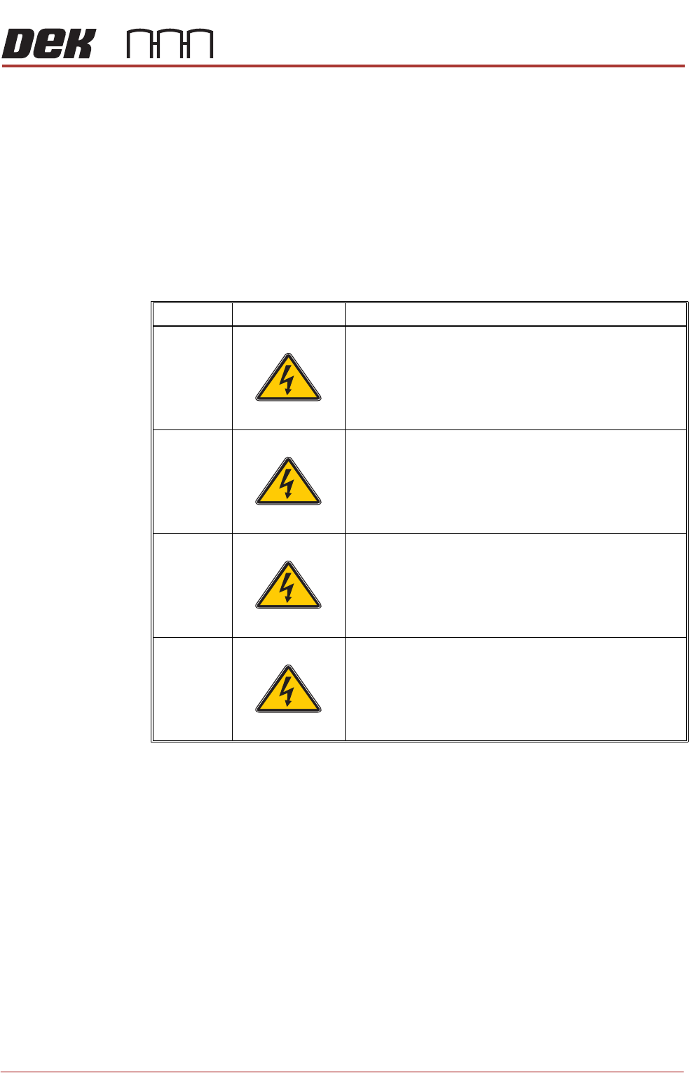
Type Symbol Definition
1 Equipment is fully de-energized
2 Equipment is energized. Energized circuits are covered or
insulated. Work is performed at a remote location to pre-
clude accidental shock
3 Equipment is energized. Energized circuits are exposed and
accidental contact is possible. Potential exposures are less
than 30 volts rms, 42.4 volts peak to peak, 60 volts dc, or 240
volt-amps in dry locations
4 Equipment is energized. Energized circuits are exposed and
accidental contact is possible. Potential exposures are
greater than 30 volts rms, 42.4 volts peak to peak, 60 volts
dc, 240 volt-amps in dry locations, or radio frequency (rf) is
present
SEMI 1
SEMI 2
SEMI 3
SEMI 4
INSTALLATION APPENDIX
COVERS
2.10 Appendix to Micron Technical Manuals Chapter Issue 1 Feb 15
COVERS
Rear Corner
Panels
To remove the rear corner panels, carry out the following:
1. Remove the Left and Right Hand Safety Covers.
2. Using a 4mm Allen key, undo the appropriate captive screws.
3. Lift the panel clear of the location pins that locate the panel to the printer
frame, taking care not to damage the earth cable.
4. Gain access to the rear of the EMO switch.
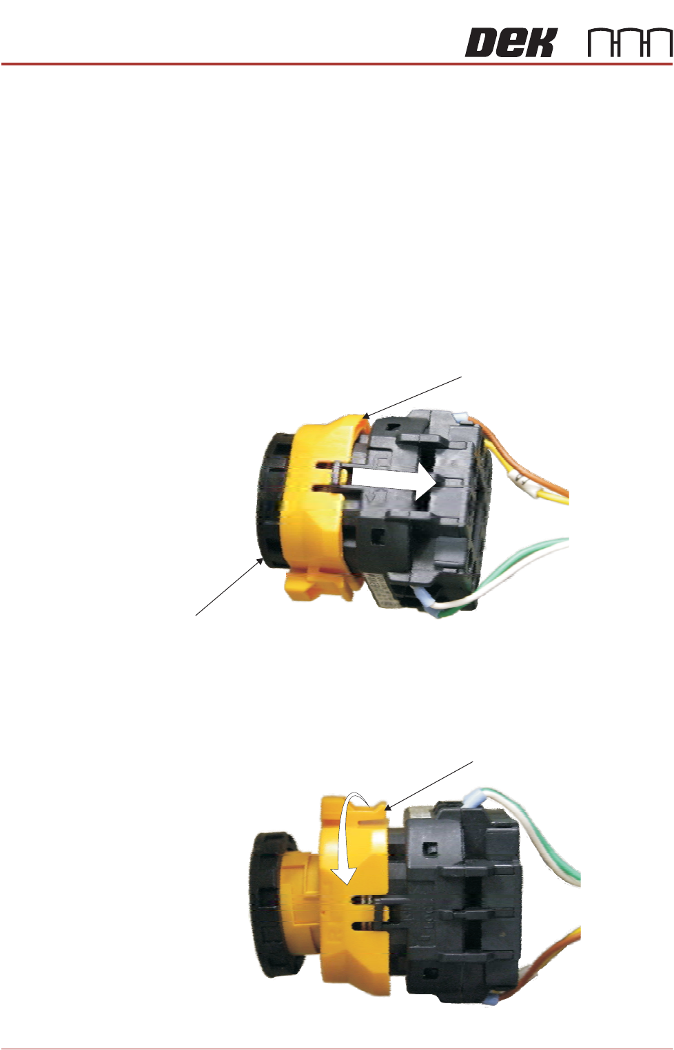
5. To disconnect the EMO carry out the following:
a. Locate the yellow locking collar at the rear of the switch.
b. Slide the collar rearwards towards the switch contact assembly against
spring pressure.
c. Viewed from the rear of the switch, rotate the locking collar anticlockwise
to release the contact assembly from the switch body.
Locking Collar
EMO Switch
View on Rear EMO Switch
View on Rear EMO Switch
Locking Collar