Gemini Semi Appendix Manual.pdf - 第31页
INSTALLATION APPENDIX EXTERNAL SERVICES Chapter Issue 1 Feb 15 Appendix to Micron Technical Manuals 2.13 ASM requires additional machine sup ply protection with the fitment of an external double pole circuit breaker conf…
INSTALLATION APPENDIX
EXTERNAL SERVICES
2.12 Appendix to Micron Technical Manuals Chapter Issue 1 Feb 15
EXTERNAL SERVICES
Pneumatic Supply The machine requires a pneumatic supply of clean, non lubricated air which
should maintain a minimum pressure 5 Bar and a maximum of 7 Bar.
The air should be to ISO 8573.1 standard, quality class 2.3.3, where:
• 2 dirt = 1 micron
• 3 water = -20°C pressure dewpoint
• 3 oil = 1mg/m3
If an emergency stop is initiated via an EMO push button switch, the pneumatic
supply is closed off and any pressurised air remaining within the machine’s
system is vented via the pneumatic dump valve.
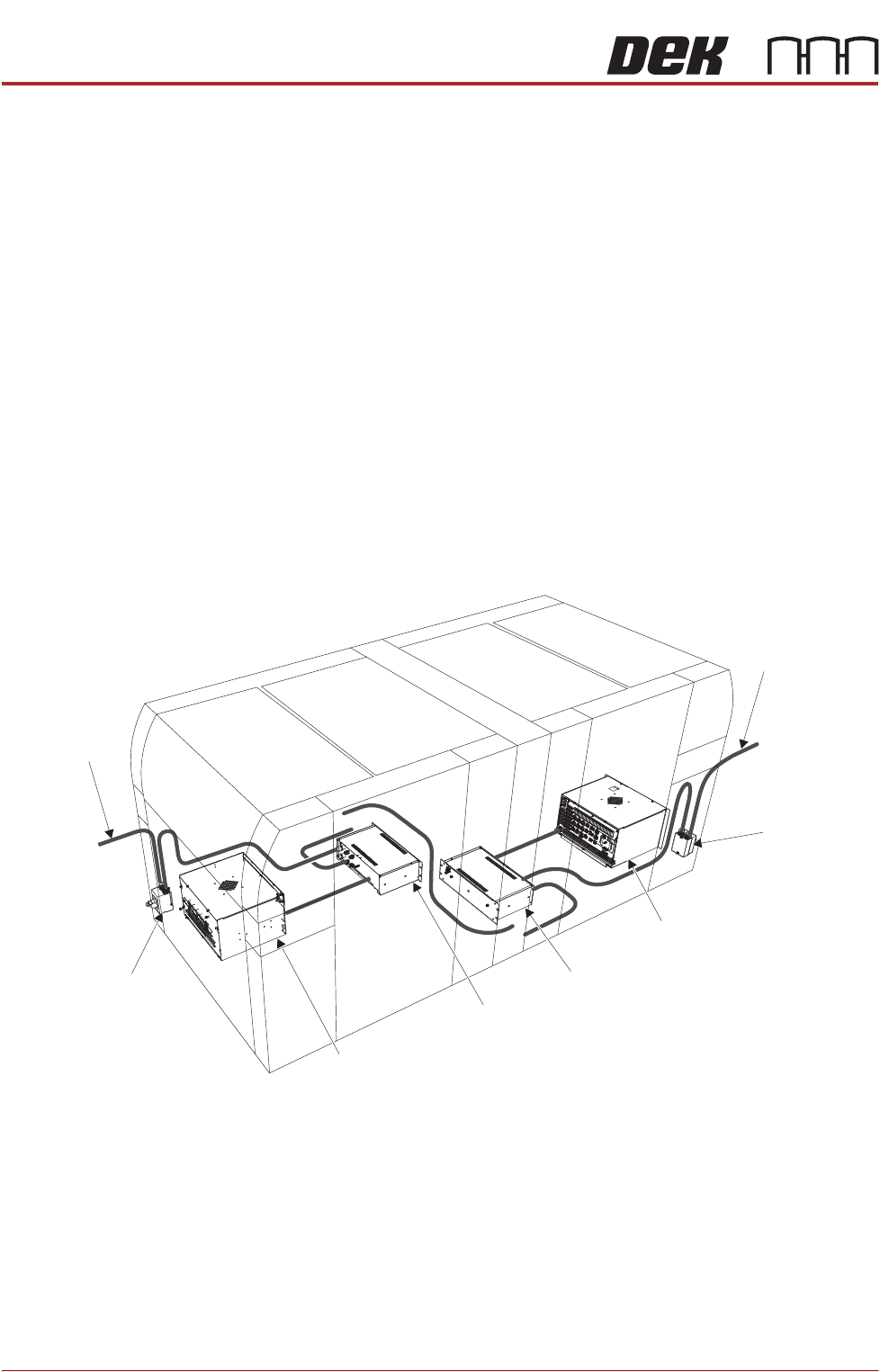
Electrical Supply The factory mains supply for the machine is routed through the front panel
mounted mains isolator switch to the M39 EMO enclosure. If both EMO push
button switches are de-activated and the Start button has been pressed mains
voltage is applied to the M37 power supply enclosure. From the enclosure
various low voltages are distributed throughout the machine.
Figure 2-3 Mains Electrical Supply
The machine operates on 100V to 240V + 10% 50/60Hz single phase ac mains,
current rating 10A or 2.4Kw.
NOTE
The voltage selector of the VF35i vacuum filtration unit needs to be set to the
factory mains supply. This is carried out in the Machine Preparation Chapter of
the Micron Installation Manual.
ASM recommends a power supply capacity of 2.4KVA or greater.
From Factory
Mains Supply
Mains Isolator
Switch
M39 EMO Enclosure
M37 Power
Supply Enclosure
M37 Power
Supply Enclosure
Mains Isolator
Switch
From Factory
Mains Supply
M39 EMO Enclosure
INSTALLATION APPENDIX
EXTERNAL SERVICES
Chapter Issue 1 Feb 15 Appendix to Micron Technical Manuals 2.13
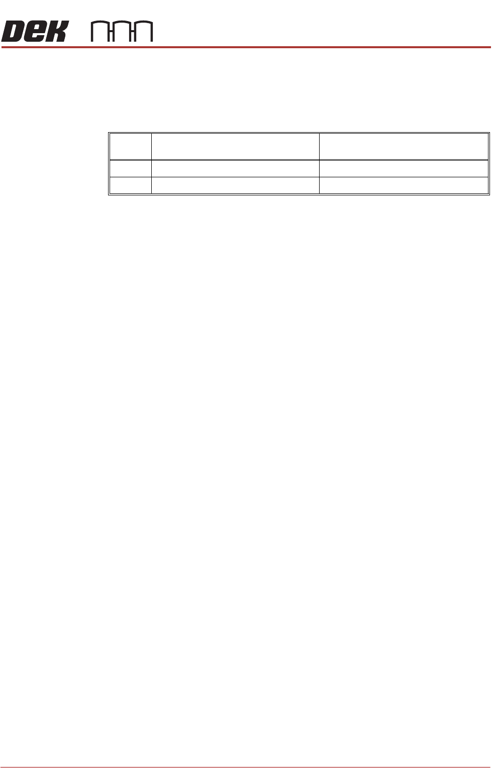
ASM requires additional machine supply protection with the fitment of an
external double pole circuit breaker conforming to national, federal or local
legislation. ASM recommends that the external circuit breaker is fitted near the
DEK printer and within easy reach of the operator. Use the following table to
ensure the recommended circuit breaker is used:
NOTE
An over current circuit breaker protects both the machine’s internal wiring and
components from overheating or catching fire during fault conditions. Under no
circumstances must a circuit breaker of value greater than 25 Amps be fitted.
Equipment If the equipment is used in a manner not specified by the manufacturer, the
protection provided by the equipment may be impaired.
This equipment should be used in accordance with the operating instructions.
ASM absolves itself of all responsibility if the machine is not used within its
operating envelope or for it’s intended purpose.
Voltage Value of Wall Mounted Circuit Breaker
(without Internal Vacuum Unit)
Value of Wall Mounted Circuit Breaker
(with Internal Vacuum Unit)
115V 10 Amp 25 Amp
230V 4/6 Amp 13/16 Amp
INSTALLATION APPENDIX
CENTRE OF GRAVITY AND SEISMIC ANCHORAGE
2.14 Appendix to Micron Technical Manuals Chapter Issue 1 Feb 15
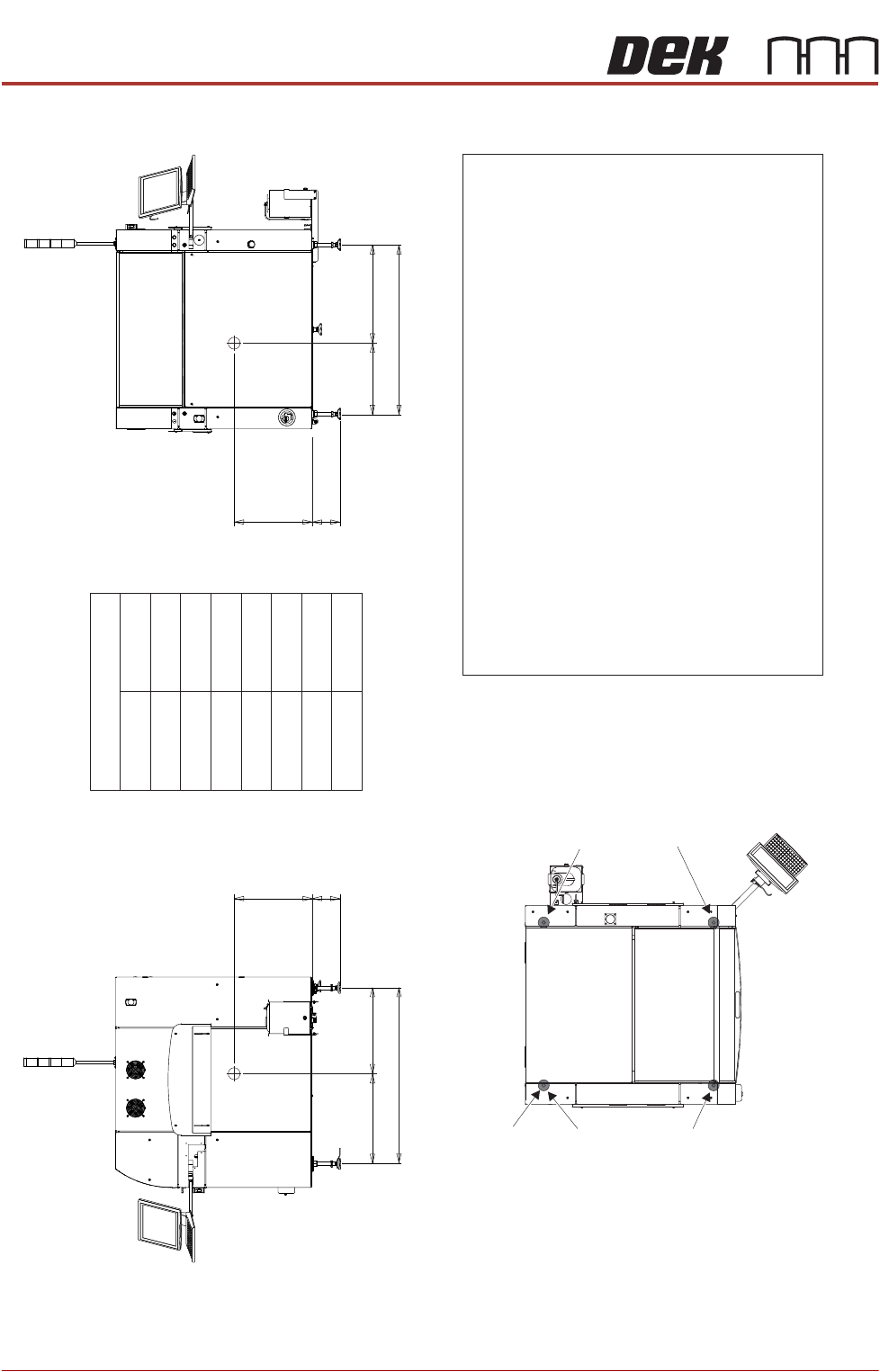
CENTRE OF GRAVITY AND SEISMIC ANCHORAGE
Side View (right)
CG
L3d
b
h
c
Front View
CG
L2a
b
h
L1
Centre of Gravity
a
b
c
d
h
L1
L2
L3
188mm
548mm
Plan View
Centre of Gravity
Seismic Anchorage
Machine Feet
(in 4 positions)
Min = - kg59
Max = kg409
Min = - kg74
Max = kg378
Min = - kg62
Max = 40 kg6
Min = - kg73
Max = kg373
Seismic Anchorage
The calculations for the downward and upward force of the feet
is calculated in line with the 1997 Uniform Building Code and
SEMI S2-0703. Results indicate that under worse circumstances
(calculation for hazardous fluids) an upward lifting force has to be
expected and it is strongly recommended to secure the machine
directly to the floor.
NOTE
In the figure on the left, negative numbers are upward loads and
positive numbers are downward loads.
Appropriate attachment points may be fitted to the front and rear
of the machine base frame. For more information, contact DEK
Printing Machines.
Alternatively, the supplied machine feet can be replaced with feet
incorporating holes allowing the feet to be secured directly to the floor.
Additional seismic calculations must be undertaken for the floor and
any anchor points that are used.
The length of the machine feet (measurement in the figures above)b
must not exceed 1 mm to meet seismic anchorage calculations.88
1106mm
592mm
5mm79
514mm
571mm
1150mm