Gemini Semi Appendix Manual.pdf - 第33页
INSTALLATION APPENDIX MAINTENANCE TASK CLEARA NCE Chapter Issue 1 Feb 15 Appendix to Micron Technical Manuals 2.15 MAINTENANCE T ASK C LEARANCE Maintenance T ask Clearance For maintenance tasks SEMI S8-0712a recommends c…
INSTALLATION APPENDIX
CENTRE OF GRAVITY AND SEISMIC ANCHORAGE
2.14 Appendix to Micron Technical Manuals Chapter Issue 1 Feb 15
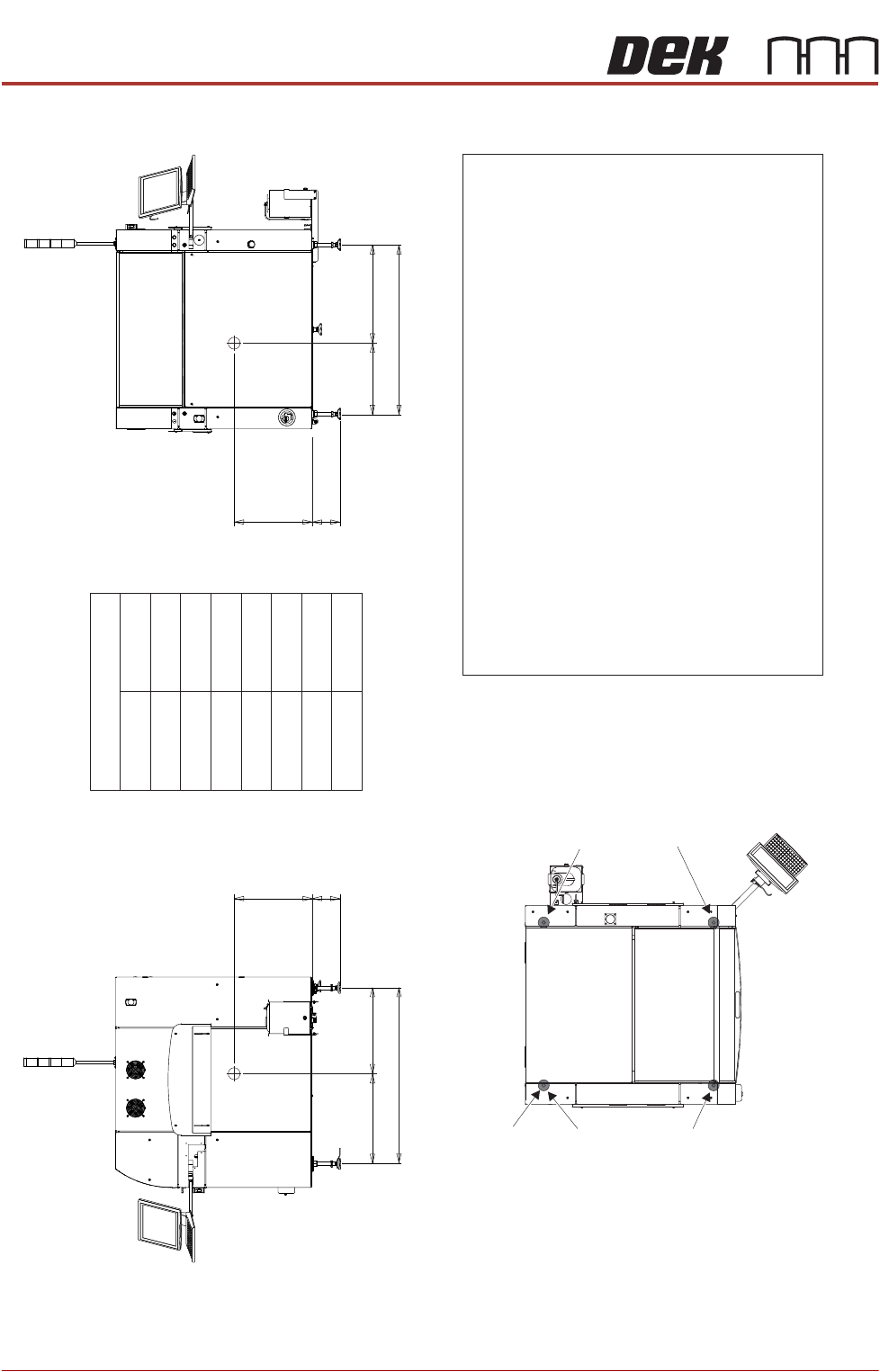
CENTRE OF GRAVITY AND SEISMIC ANCHORAGE
Side View (right)
CG
L3d
b
h
c
Front View
CG
L2a
b
h
L1
Centre of Gravity
a
b
c
d
h
L1
L2
L3
188mm
548mm
Plan View
Centre of Gravity
Seismic Anchorage
Machine Feet
(in 4 positions)
Min = - kg59
Max = kg409
Min = - kg74
Max = kg378
Min = - kg62
Max = 40 kg6
Min = - kg73
Max = kg373
Seismic Anchorage
The calculations for the downward and upward force of the feet
is calculated in line with the 1997 Uniform Building Code and
SEMI S2-0703. Results indicate that under worse circumstances
(calculation for hazardous fluids) an upward lifting force has to be
expected and it is strongly recommended to secure the machine
directly to the floor.
NOTE
In the figure on the left, negative numbers are upward loads and
positive numbers are downward loads.
Appropriate attachment points may be fitted to the front and rear
of the machine base frame. For more information, contact DEK
Printing Machines.
Alternatively, the supplied machine feet can be replaced with feet
incorporating holes allowing the feet to be secured directly to the floor.
Additional seismic calculations must be undertaken for the floor and
any anchor points that are used.
The length of the machine feet (measurement in the figures above)b
must not exceed 1 mm to meet seismic anchorage calculations.88
1106mm
592mm
5mm79
514mm
571mm
1150mm
INSTALLATION APPENDIX
MAINTENANCE TASK CLEARANCE
Chapter Issue 1 Feb 15 Appendix to Micron Technical Manuals 2.15
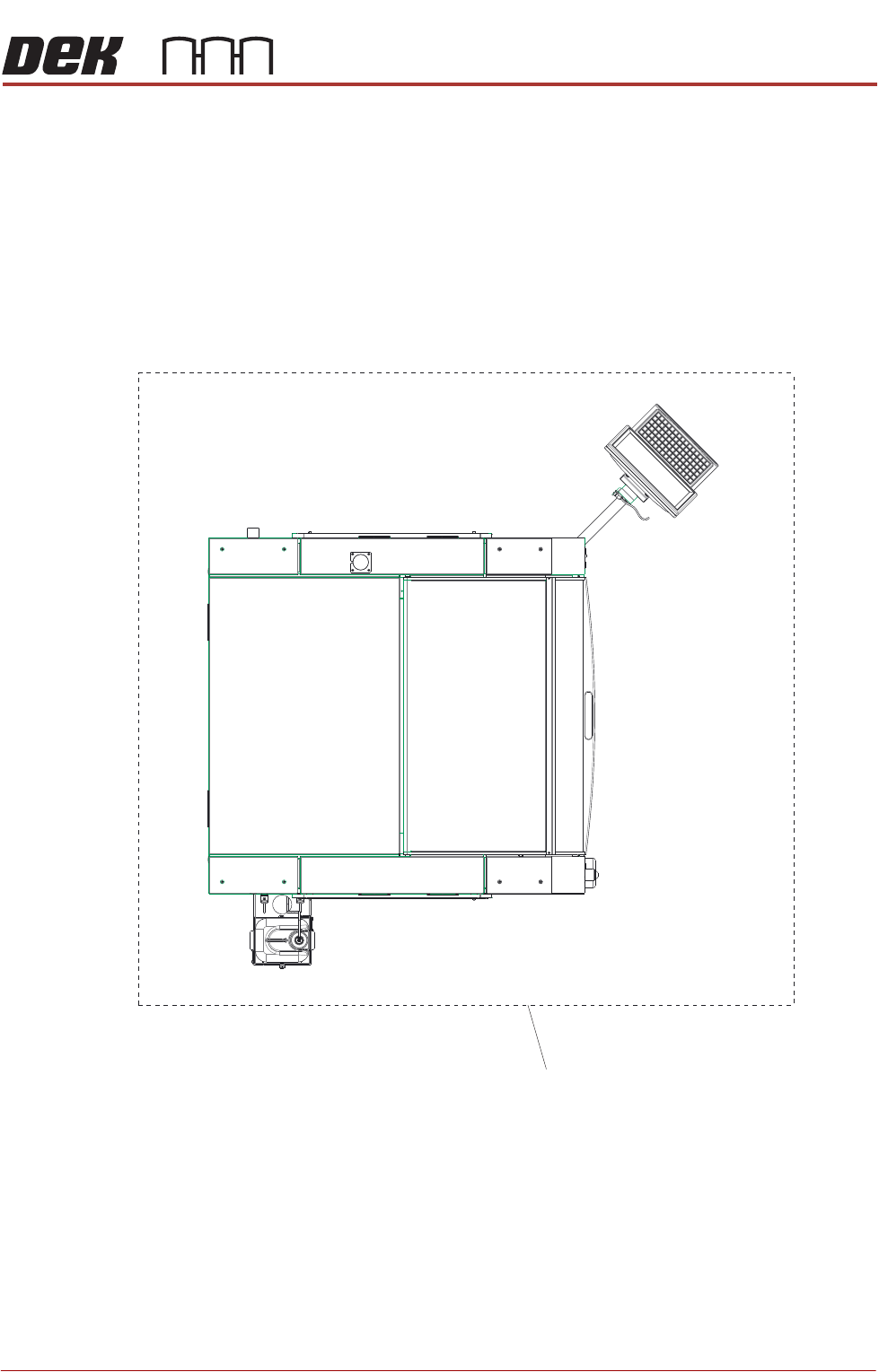
MAINTENANCE TASK CLEARANCE
Maintenance Task Clearance
For maintenance tasks SEMI S8-0712a recommends clearance
of at least 1.2m (48in.) from machine.
Maintenance Task
Clearance
INSTALLATION APPENDIX
PRE POWER UP CHECKS
2.16 Appendix to Micron Technical Manuals Chapter Issue 1 Feb 15
PRE POWER UP CHECKS
Having removed the transit brackets and assembled the machine, prepare to
install the machine, as follows:
Electrical Test Before the machine is connected to the factory electrical supply, the following
electrical tests must be performed:
1. Ensure the mains isolator switch is in the OFF position.
2. Remove the Front Left Hand Lower Corner Panel of the machine to gain
access to the mains isolator switch.
3. Remove the front cover of the mains isolator switch.
4. Loosen the two blue coloured terminal cover securing screws and remove
the cover.
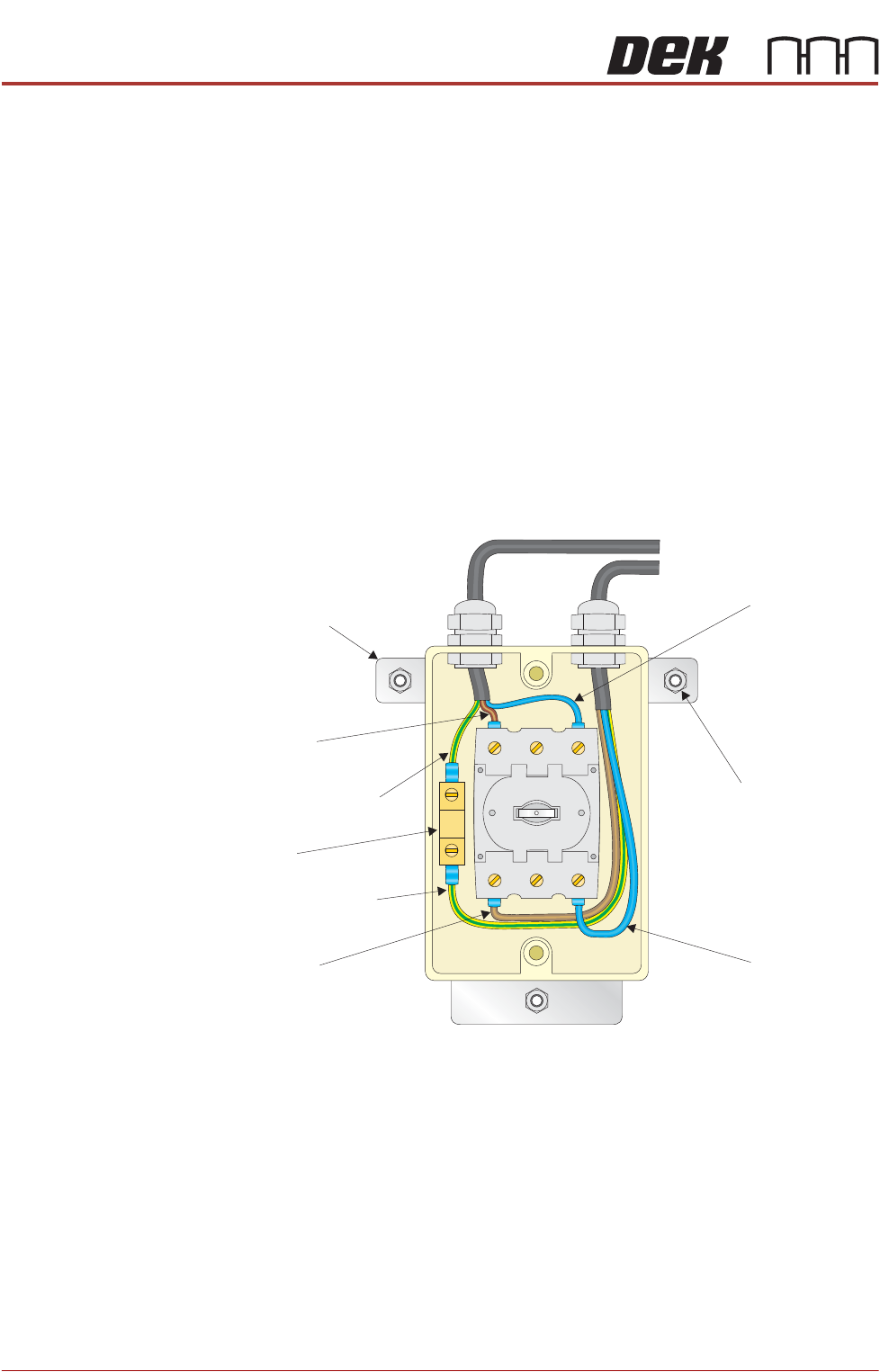
5. Perform a visual inspection of the mains isolator switch ensuring the follow-
ing:
a. The earth input and earth output cables are connected to the earth tag.
b. The live input is connected to the top of the isolator switch on the left hand
side.
c. The live output is connected to the bottom of the isolator switch on the left
hand side.
d. The neutral input is connected to the top of the isolator switch on the right
hand side.
e. The neutral output is connected to the bottom of the isolator switch on the
right hand side.
6. Ensure that all seven cables are secure and no bare wires are showing.
Neutral (Blue)
Input
Isolator Mount
Securing Nut
(in 3 positions)
Isolator Mount
Live (Brown)
Input
Earth (Green/Yellow)
Input
Earth (Green/Yellow)
Output
Earth Tag
Live (Brown)
Output
Neutral (Blue)
Output