Gemini Semi Appendix Manual.pdf - 第44页
TECHNICAL REFERENCE APPENDIX M39 EMERGENCY MACHINE OFF ENCLOSURE 3.6 Appendix to Micron Technical Manuals Chapter Issue 1 Feb 15 M39 Rear Panel M39SK1 M39SK2 Connector Description Connector Description M39SK1 Front EMO P…

TECHNICAL REFERENCE APPENDIX
M39 EMERGENCY MACHINE OFF ENCLOSURE
Chapter Issue 1 Feb 15 Appendix to Micron Technical Manuals 3.5
Emergency
Machine Off
The emergency machine off circuit comprises the following:
• The E Stop Relay
•Start Switch
• Front EMO Switch
• Rear EMO Switch
• Pneumatic Dump Valve
• EMO Safe PSU
• Contactors CON1 and CON2
Powering Up When the mains isolator is switched on mains input voltage is supplied to the
M39 enclosure. The input voltage is distributed within the enclosure via Terminal
Blocks TB1, TB2 and TB3. Initially the input voltage is applied to the open
contacts of Contactors CON1 and CON2. The input voltage is also distributed
via fused Terminal Blocks TB6 and TB7 to the EMO Safe PSU. The PSU
produces a +24V dc which is distributed via Terminal Block TB4.
When the Start Button is pressed, the supply to the E-Stop relay is complete
and the relay energises. The relay contacts close supplying 24V dc via Terminal
Block TB5 to the solenoids of CON1 and CON2. The contactors are energised
and the closed contacts complete the circuit to the M37 enclosure allowing the
machine is power up.
An additional set of contactor contacts supply 24V dc to the pneumatic dump
valve allowing the factory pneumatic supply to be applied to the machine.
EMO Operation If either of EMO push button switches are operated the E-Stop relay is de-
energised causing the 24V dc supply to the solenoids of CON1 and CON2 to
be broken. Contacts of CON1 and CON2 are opened, breaking the mains input
voltage to the M37 enclosure, immediately removing electrical power from the
machine. Also the 24V dc supply to the pneumatic dump valve is removed de-
energising the valve. The factory pneumatic supply is removed from the
machine and any residual machine pneumatic pressure is vented safely to
atmosphere.
TECHNICAL REFERENCE APPENDIX
M39 EMERGENCY MACHINE OFF ENCLOSURE
3.6 Appendix to Micron Technical Manuals Chapter Issue 1 Feb 15
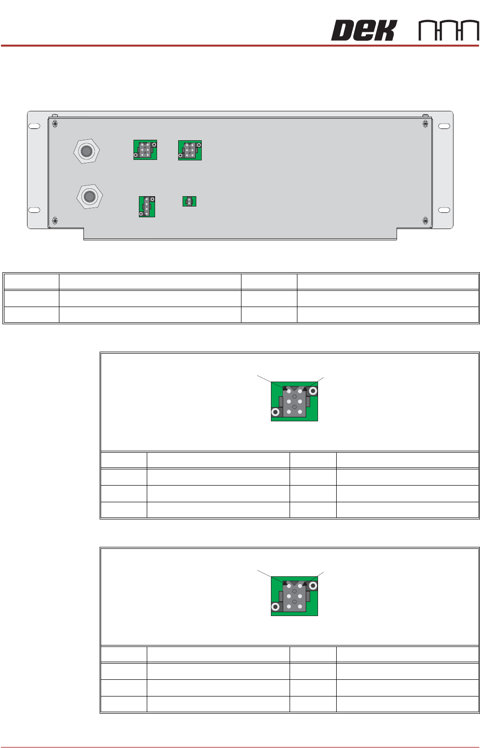
M39 Rear Panel
M39SK1
M39SK2
Connector Description Connector Description
M39SK1 Front EMO Push Button M39SK3 Start Push Button
M39SK2 Rear EMO Push Button M39SK4 Pneumatic Dump Valve
View on Rear Panel
M39SK1
M39SK4
M39SK2
M39SK3
Mains In
Mains Out
Pin No. Signal Pin No. Signal
1 Link to Terminal S21 - E-Stop Relay 4 N/C
2 Link to Terminal S21 - E-Stop Relay 5 Link to M39SK2 Pin 1
3 Link to M39SK2 Pin 2 6 N/C
1
4
6 Way Trident
Pin No. Signal Pin No. Signal
1 Link to M39SK1 Pin 5 4 N/C
2 Link to M39SK1 Pin 3 5 Link to Terminal S22 - E-Stop Relay
3 Link to Terminal S12 - E-Stop Relay 6 N/C
1
4
6 Way Trident
TECHNICAL REFERENCE APPENDIX
M39 EMERGENCY MACHINE OFF ENCLOSURE
Chapter Issue 1 Feb 15 Appendix to Micron Technical Manuals 3.7
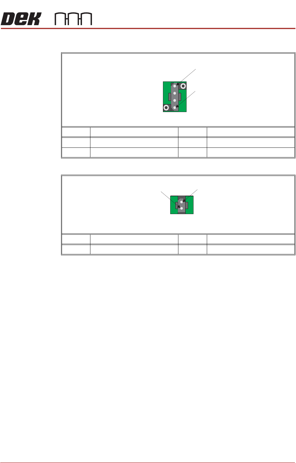
M39SK3
M39SK4
Pin No. Signal Pin No. Signal
1 Link to Terminal S33 - E-Stop Relay 3 +24V dc
2 Link to Terminal S34 - E-Stop Relay 4 0V Return
Pin No. Signal Pin No. Signal
1 +24V dc 2 0V Return
1
4
4 Way Trident
1
2
2 Way Trident