Gemini Semi Appendix Manual.pdf - 第46页
TECHNICAL REFERENCE APPENDIX M37 POWER SUPPLY ENCLOSURE 3.8 Appendix to Micron Technical Manuals Chapter Issue 1 Feb 15 M37 POWER SUPPL Y ENCLOSURE Item Description Item Desc ription 1 Front Cover Interlock 3 T wo Button…
TECHNICAL REFERENCE APPENDIX
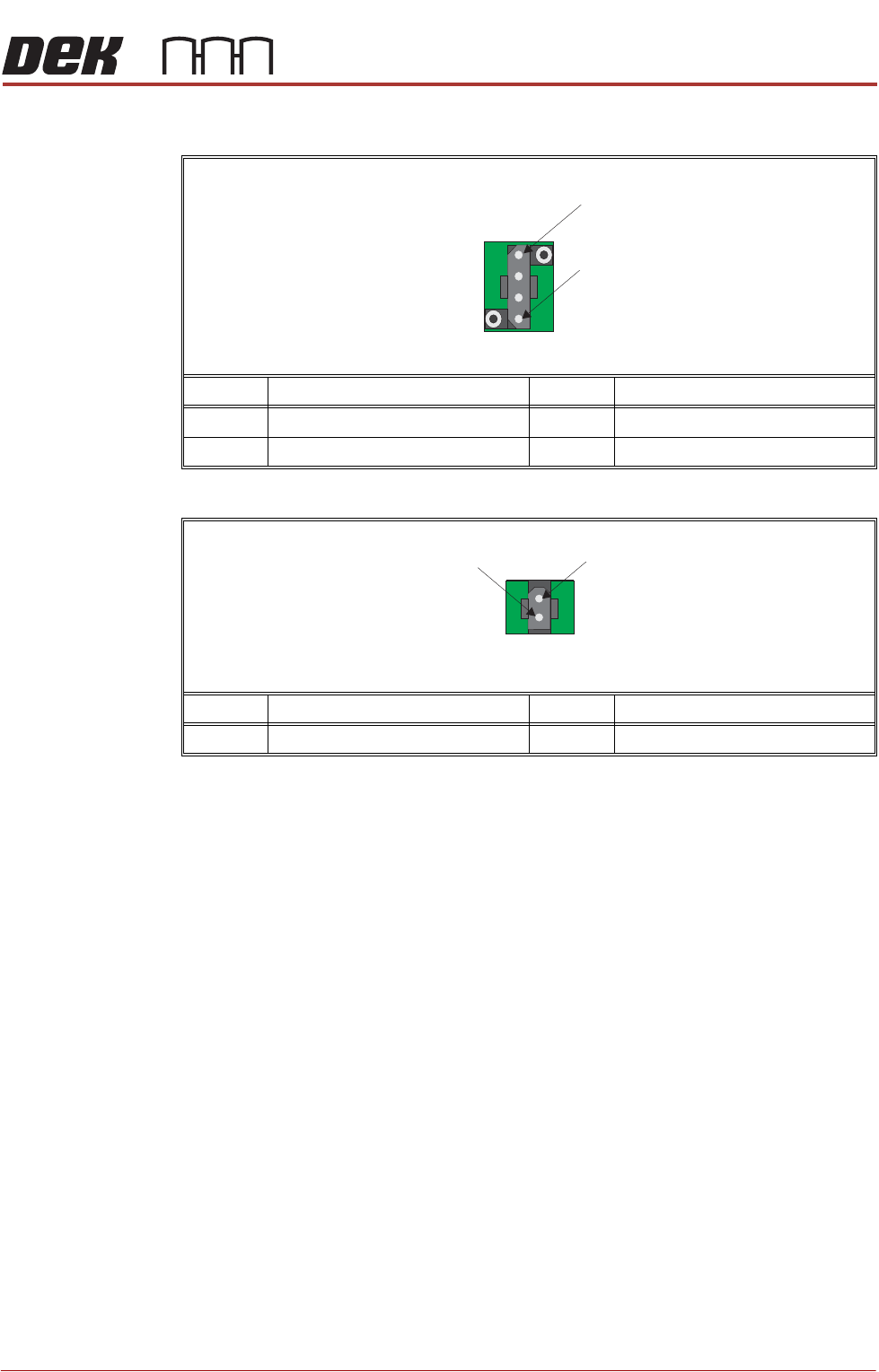
M39 EMERGENCY MACHINE OFF ENCLOSURE
Chapter Issue 1 Feb 15 Appendix to Micron Technical Manuals 3.7
M39SK3
M39SK4
Pin No. Signal Pin No. Signal
1 Link to Terminal S33 - E-Stop Relay 3 +24V dc
2 Link to Terminal S34 - E-Stop Relay 4 0V Return
Pin No. Signal Pin No. Signal
1 +24V dc 2 0V Return
1
4
4 Way Trident
1
2
2 Way Trident
TECHNICAL REFERENCE APPENDIX
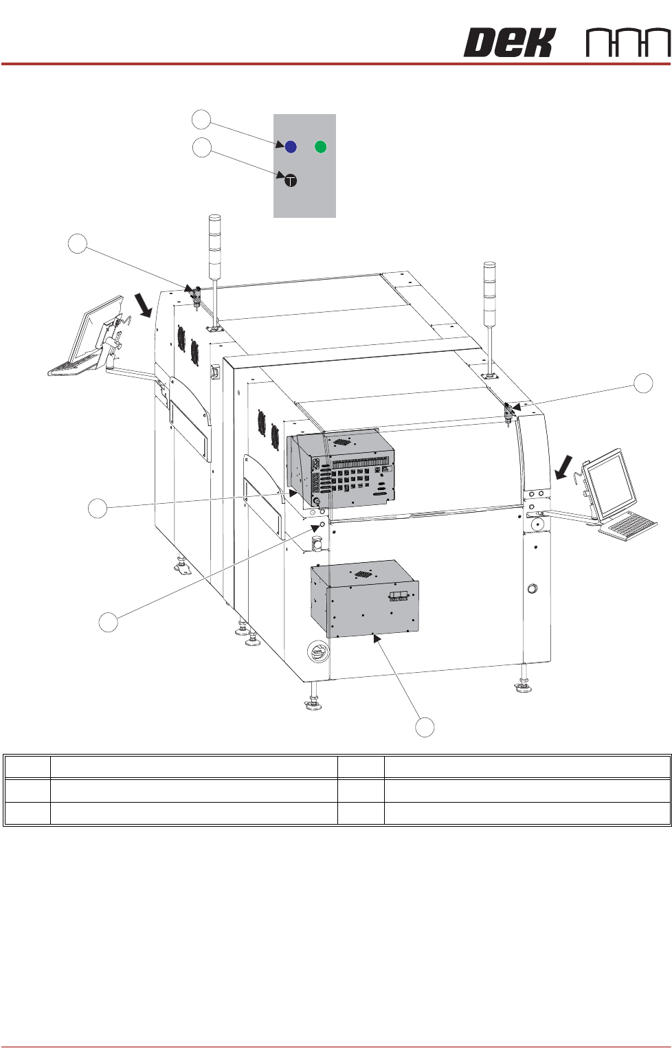
M37 POWER SUPPLY ENCLOSURE
3.8 Appendix to Micron Technical Manuals Chapter Issue 1 Feb 15
M37 POWER SUPPLY ENCLOSURE
Item Description Item Description
1 Front Cover Interlock 3 Two Button Control
2 M37 Power Supply Enclosure 4 System Button
View on Arrow A
4
2
1
A
A
3
3
1
2

TECHNICAL REFERENCE APPENDIX
M37 POWER SUPPLY ENCLOSURE
Chapter Issue 1 Feb 15 Appendix to Micron Technical Manuals 3.9
WARNING
LETHAL VOLTAGE. DANGEROUS VOLTAGES EXIST IN THIS EQUIPMENT.
ENSURE ALL ELECTRONIC COVERS AND MAIN MACHINE COVERS ARE
FITTED BEFORE OPERATING THIS EQUIPMENT.
Mains input power (115V to 230V) to the machine is routed via the mains isolator
switch and the M39 EMO enclosure. From the M39 enclosure it is fed to the M37
power supply crate, through the cable gland at the rear panel, to the three
terminal blocks TB1 (live), TB2 (neutral) and TB3 (earth). From the terminal
blocks mains power is supplied to the following:
• M37SK31 PC Supply
• M37SK32 Monitor Supply
• M37SK33 Spare
• M37SK34 Spare
• M37SK35 Internal Vac Pump via Mains Filter and CB34
• PSU
PSU is a Switched Mode Power Supply Unit (SMPSU) which converts the ac
into the following dc supplies:
•+24V US
• +24V SW
•+5.5V
•+12V
•-12V
•+42V
The dc supplies from the PSU is fed to the power distribution PCB. Mounted
on the power distribution PCB is the PSU monitor board which enables moni-
toring of the power supplies.
A printhead cover loop consisting front cover interlock, interlock blanking plug
and E Stop relay are fitted to ensure motor power is removed if the front
printhead cover is opened.
A two handed safety relay, left jog button and right jog button are fitted to enable
certain functions to be performed with the front printhead cover open.
NOTE
Following a service visit that involves any disturbance of components in the
mains voltage circuit an electrical test as detailed in the Pre Power section of
the Transportation chapter must be undertaken. Before testing ensure that the
machine is isolated from the factory supply and that any external equipment (ie
upline and downline conveyors) are disconnected.