Gemini Semi Appendix Manual.pdf - 第69页
TECHNICAL REFERENCE APPENDIX CALIBRATIONS Chapter Issue 1 Feb 15 Appendix to Micron Technical Manuals 3.31 the following graphic: 14. Fit the calibra tion jig to the front squeeg ee position. 15. Fit the squeegee pressur…
TECHNICAL REFERENCE APPENDIX
CALIBRATIONS
3.30 Appendix to Micron Technical Manuals Chapter Issue 1 Feb 15
CALIBRATIONS
Squeegee Module
Squeegee Pressure
Calibration
Squeegee pressure calibration is carried out on machines after the following
circumstances:
• The squeegee mechanism is replaced
• The strain gauge bridge in the squeegee mechanism is replaced
• The rising table sensors have been replaced or adjusted
A force meter calibration jig and squeegee pressure plate are required to
perform the squeegee pressure calibration.
NOTE
1. Ensure that the rising table print reference height is set correctly before
commencing, (the calibration relies upon accurate positioning of the table to
make a reference).
2. Ensure that the Pressure Hardware parameter in Maintenance\Machine
Setup\Options is set to FITTED.
Use the following procedure to calibrate the squeegee pressure:
WARNING
BOARD CLAMPS. EXTREME CARE MUST BE EXERCISED WHEN WORKING IN
THE TOOLING AREA OF THE MACHINE TO AVOID INJURY. THE FOILS ON THE
FRONT AND REAR BOARD CLAMPS ARE VERY SHARP.
1. From the Ready page, select Unload Screen.
2. Open the front printhead cover.
3. Remove the screen from the machine.
4. Remove the tooling (if fitted) from the manual tooling plate.
5. Close the front printhead cover.
6. Press the System button.
7. Select Maintenance.
8. Select Calibrations.
9. Select Pressure.
10.Select Calibrate Readings.
The rails are checked for the presence of a board, the print carriage moves
to the calibration position, the rear rail moves to home position, the table
homes and the board clamps are closed.
11. The machine cover is unlocked and the message ‘Fit the pressure calibra-
tion rig’ is displayed with the following window:
12.Open the front printhead cover.
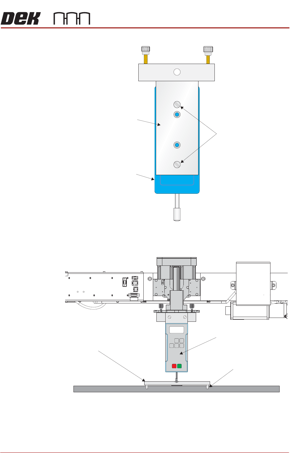
13.Ensure that the calibration jig is secured to the mounting plate as shown in
SEMI 2
CALIBRATION DATA
Gain Factor
1.02
TECHNICAL REFERENCE APPENDIX
CALIBRATIONS
Chapter Issue 1 Feb 15 Appendix to Micron Technical Manuals 3.31
the following graphic:
14.Fit the calibration jig to the front squeegee position.
15. Fit the squeegee pressure plate to the rising table ensuring that the locating
dowels insert the holes of the rising table.
Mounting Plate
Mounting Holes
Calibration Jig
A
A
S
S
View on Front Squeegee MechanismUnderneath Rising Table and
View on Front of Rising Table and Squeegee Mechanism
Squeegee Pressure Plate
Locating Dowel
(in 2 positions)
O
OFF
I
ON
UNITS
Zero
MAX TXD
RESET
00.00
Portable Force Gauge
(Calibration Jig)
TECHNICAL REFERENCE APPENDIX
CALIBRATIONS
3.32 Appendix to Micron Technical Manuals Chapter Issue 1 Feb 15
NOTE
During the squeegee pressure calibration the dwell height of the rear
squeegee is 15mm regardless of the set up value. This height is set during
calibration only.
16.Switch the force meter ON and check the reading is 0kg, (ensure the force
meter is not in contact with the squeegee pressure plate).
17.Select Continue.
18.The front squeegee mechanism steps down until a change in pressure is
detected and continues stepping down until the pressure value stored on the
machine is reached. If the calibration jig displays 10kg, go to Step 25.
19.Select Jog Rig.
20.Use the left and right jog buttons to move the front squeegee mechanism up
or down until the calibration jig displays 10kg.
NOTE
Achieving exactly 10kg may not be possible as some calibration jigs display
down to three decimal places.
21.Select Set Calib..
22.Select Exit.
23.The front squeegee mechanism moves to the home position. The message
‘Confirm that the pressure calibration jig has been removed.’ is dis-
played.
24.Remove the calibration jig and the squeegee pressure plate from the
machine. On completion select Yes, the table resets, the print carriage
moves to home position, board clamps open and the rear rail moves to the
board width setting.
25.Carry out the Squeegee Reference Height calibration.
Squeegee
Reference Height
Squeegee reference height is carried out on machines after the following
circumstances:
• Squeegee pressure calibration
• Squeegee change
Use the following procedure to set the squeegee reference height:
1. If a Ptest.dat file is not required, go to Step 7.
2. Select Maintenance.
3. Select Test Cycles.
4. Select Data Logging On.
5. Select Back.
6. Select Back.
7. Select Setup Product.
8. Select Squeegees.
9. Select Unload Screen.
10.Open the front printhead cover.
SEMI 2