Gemini Semi Appendix Manual.pdf - 第73页
TECHNICAL REFERENCE APPENDIX CALIBRATIONS Chapter Issue 1 Feb 15 Appendix to Micron Technical Manuals 3.35 Camera System Module Board S top X Of fset Check W ARNING BOARD CLAMPS. EXTREME CARE MUST BE EXERCISED WHEN WORK …

TECHNICAL REFERENCE APPENDIX
CALIBRATIONS
3.34 Appendix to Micron Technical Manuals Chapter Issue 1 Feb 15
2. Under My Computer, locate and open the E:\Log\Ptest.dat file.
The figure below gives a representation of the Ptest.dat file.
(Fwd Press Flood)(Rear Press Flood)(Flood Ref. Height)(Front Ref. Height)(Rear Ref. Height)
33.1004 31.9668 3951.6971 3947.7037 3935.1178
(steps)
(kg)
Rear Squeegee
4301.000000
4286.000000
4271.000000
4256.000000
4241.000000
4226.000000
4211.000000
4196.000000
4181.000000
4166.000000
4151.000000
4136.000000
4121.000000
4106.000000
4091.000000
4076.000000
4061.000000
4046.000000
4031.000000
4016.000000
22.480215
21.961
163
21.503175
21.045188
20.587201
20.068149
19.640694
19.182706
18.724719
18.266732
17.747680
17.289692
17.801172
16.343185
15.885198
15.396678
14.908158
14.480703
13.992184
13.564729
Front Squeegee
(steps)
(kg)
4039.000000
4324.000000
22.388617
21.930630
21.472643
21.045188
20.587201
20.129213
19.640694
19.213239
18.694187
18.266732
17.839277
17.350757
16.892770
16.465315
16.007328
15.579873
15.121886
14.724963
14.236444
13.778456
4309.000000
4294.000000
4279.000000
4264.000000
4249.000000
4234.000000
4219.000000
4204.000000
4189.000000
4174.000000
4159.000000
4144.000000
4129.000000
41
14.000000
4099.000000
4084.000000
4069.000000
4054.000000
NOTE
Text shown in italics is not
displayed in the Ptest.dat file.

TECHNICAL REFERENCE APPENDIX
CALIBRATIONS
Chapter Issue 1 Feb 15 Appendix to Micron Technical Manuals 3.35
Camera System
Module
Board Stop X Offset Check
WARNING
BOARD CLAMPS. EXTREME CARE MUST BE EXERCISED WHEN WORKING IN
THE TOOLING AREA OF THE MACHINE TO AVOID INJURY. THE FOILS ON THE
FRONT AND REAR BOARD CLAMPS ARE VERY SHARP.
1. Select Open Cover Commands.
2. Select Carriage To Rear.
3. Select Unload Screen.
4. Open the front printhead cover.
5. Remove the screen.
6. Close the front printhead cover.
7. Press the System button.
8. Select Back.
9. Select Maintenance.
10.Select Diagnostics.
11. Use Next or Previous to highlight Camera Axes.
12.Select Select Module.
13.Use Next or Previous to highlight Home Camera X Axis.
14.Select Run Diagnost.
15.Use Next or Previous to highlight Home Camera Y Axis.
16.Select Run Diagnost.
17.Use Next or Previous to highlight Drive to Board Stop Position.
18.Select Run Diagnost.
19.Select Exit.
20.Use Next or Previous to highlight Rail System.
21.Select Select Module.
22.Use Next or Previous to highlight Toggle Board Stop.
23.Select Run Diagnost.
24.Open the front printhead cover.
25.Place a board onto the rails and move it up against the board stop.
26.Close the front printhead cover.
27.Press the System button.
28.Use Next or Previous to highlight Toggle Board Clamp.
29.Select Run Diagnost.
30.Use Next or Previous
to highlight T
oggle Board Stop.
31.Select Run Diagnost.
SEMI 2
TECHNICAL REFERENCE APPENDIX
CALIBRATIONS
3.36 Appendix to Micron Technical Manuals Chapter Issue 1 Feb 15
32.Select Exit.
33.Use Next or Previous to highlight Camera Axes.
34.Select Select Module.
35.Use Next or Previous to highlight Initialise Vision System.
36.Select Run Diagnost.
37.Select Exit.
38.Open the front printhead cover.
39.Place a non-magnetic rule flat against the board edge and slide a second
rule so that it abuts it and comes within the camera field of view.
40.On the vision monitor, record the distance from the board edge to the
approximate centre of the square (figure below refers). This value is the
Board Stop X Offset and should be -43.5mm ±0.5mm.
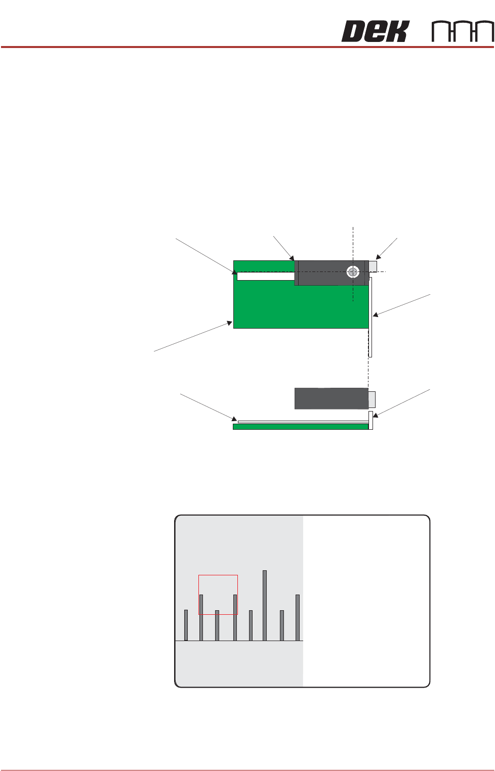
Camera
Camera Board Stop
Metric Rule
Metric Rule
Board
Metric Rule
Side View
Metric Rule
Plan View
45
43 4644